


Filter Systems
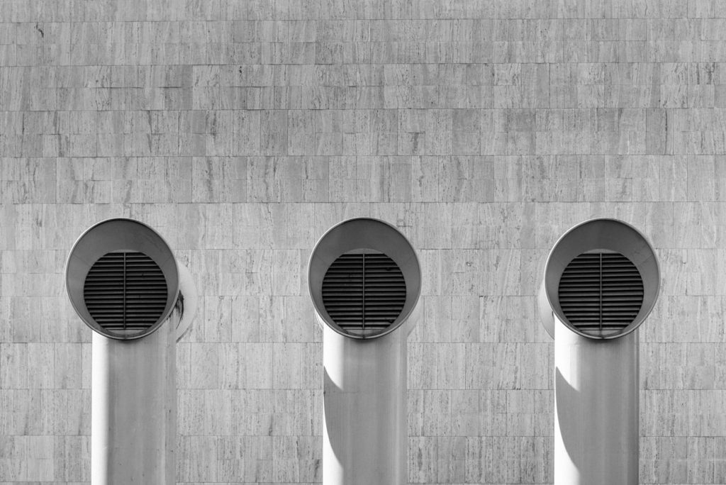
Foto by Elimende Inagella on Unsplash
The applications of filters are wide-ranging, and accordingly, the requirements for their monitoring are also diverse. For instance, the filter of a ventilation system, where even slight contamination causes a differential pressure of a few millibars, places very different demands on measurement technology compared to a cartridge filter in a hydraulic oil system. A central element across all these applications is the importance of reliable measurement. A precise measurement result, as provided by a pressure or differential pressure transmitter, or a pressure gauge, is crucial for efficient operation of the systems. This not only leads to optimization of energy consumption but also contributes to reducing operating costs and improving environmental friendliness.
Hydraulic Filters: Particles in hydraulic oil cause significant wear on moving parts such as pumps, motors, valve pistons, or cylinders. Therefore, filters in the hydraulic circuit are essential components. They are often installed in the return line to the tank, where the pressure level is low and is discharged against atmospheric pressure. The monitoring of filter contamination is carried out here by a relative pressure transmitter. For the protection of specific components, such as the hydraulic motor, filters are installed upstream of this component and their contamination is monitored by means of differential pressure measurement.
Machine Tools: In machining centers, chips are generated during metal processing, which are transported from the coolant (KSS) to the disposal facility. A chip separator separates the solid from the liquid components so that the KSS can be reused. The solid chips are recycled. Problems often arise with float switches in the chip pre-separator, which control the further transport of the belt filter. If chips accumulate, the float switch may no longer function correctly, leading to overflow of the coolant and thus to cleaning effort and increased risk of accidents. Due to our depth of manufacturing, we are able to develop tailor-made solutions and test them in our own production to ensure the reliability that our customers expect.
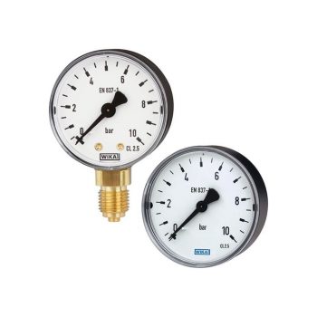
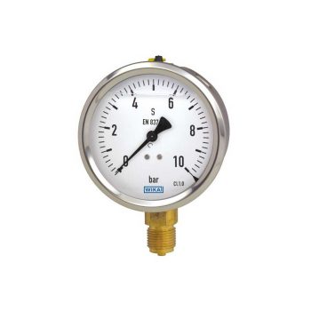
- Reliable and cost-effective
- Design per EN 837-1 or ASME B40.100
- Nominal size 40 [1 ½"], 50 [2"], 63 [2 ½"], 80 [3"], 100 [4"] and 160 [6"]
- Scale ranges to 0 ... 400 bar [0 ... 6,000 psi]
 Datasheet Datasheet |
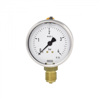
- Very good vibration and shock resistance
- Robust design
- Scale ranges to 0 ... 400 bar or 0 ... 6,000 psi
| Datasheet |
| User Manual |
- With one or two adjustable microswitches
- Shatterproof window and robust aluminium or stainless steel measuring chamber for increased requirements
- Optionally with approvals for hazardous areas
- High ingress protection, IP65, for outdoor use and processes with high condensation
- Low measuring range from 0 ... 250 mbar
| Datasheet |
| User Manual |
- Very good vibration and shock resistance
- Especially robust design
- Type approval for the shipbuilding industry
- Scale ranges to 0 ... 1,000 bar or 0 ... 15,000 psi
|
Datasheet |
| User Manual |
| User Manual |
| User Manual |
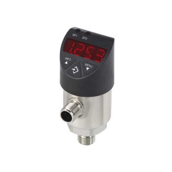
- Easily readable, robust digital display
- Intuitive and fast setup
- Easy and flexible mounting configurations
- Flexibly configurable and scalable output signals
| Datasheet |
| User Manual |
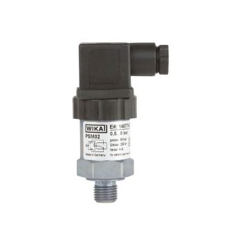
- Adjustable switch hysteresis
- Setting ranges: 0.2 … 2 bar [3 ... 30 psi] to 30 ... 320 bar [450 ... 4,600 psi] and -0.85 ... -0.15 bar [-25 inHg ... -5 inHg]
- Non-repeatability of the switch point: ≤ 2 %
- Switching functions: Normally closed, normally open or change-over contact
- Media: Compressed air, neutral and self-lubricating fluids and neutral gases
 Datasheet Datasheet
|
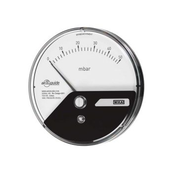
- Very small insertion depth
- Simple and fast mounting via threaded bezel
- Separated construction of measuring chamber and display area
- Integrated sealing element for direct mounting in a ventilation duct
- Individual design of dial and scale possible
| Datasheet |
| User Manual |
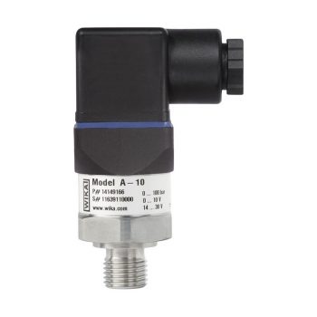
- Measuring ranges from 0 … 0.05 to 0 … 1,000 bar
- Non-linearity 0.25 % or 0.5 %
- Output 4 ... 20 mA, DC 0 ... 10 V, DC 0 ... 5 V and others
- Electrical connection: Angular connector form A and C, circular connector M12 x 1, cable outlet 2 m
- Process connection G ¼ A DIN 3852-E, ¼ NPT and others
|
Datasheet |
| User Manual |
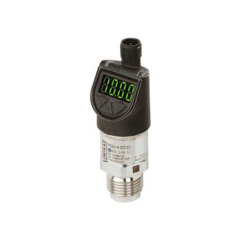
- Good/bad indication through parameterisable digital display (red/green)
- Compact size enables easy installation in narrow spaces
- Optimised design makes OEM machine integration easier
- Designed for rough demands of up to 50 g shock and -40 ... +125 °C [-40 ... +257 °F]
| Datasheet |
| User Manual |
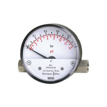
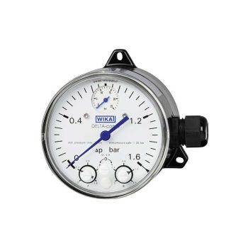
- Differential pressure measuring ranges Model 700.01: from 0 ... 400 mbar to 0 ... 10 bar Model 700.02: from 0 ... 160 mbar to 0 ... 2.5 bar
- Compact system case from stainless steel, suitable for high working pressures (static pressures) selectable, 100, 250 or 400 bar (model 700.02 up to a max. 100 bar)
- Overpressure safe either side to maximum working pressure
- System and/or case of indication may be changed locally
- Up to 2 reed contacts may also be adjusted and retrofitted locally
| Datasheet |
| User Manual |
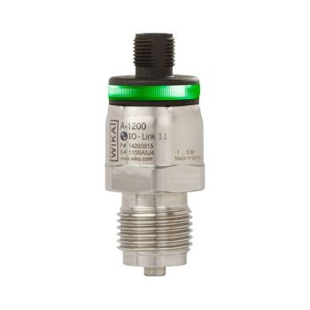
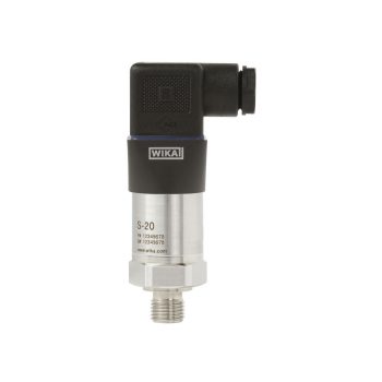
- Industry 4.0-ready IO-Link sensor improves connectivity and diagnostics
- Designed for rough demands of up to 1,000 g shock and -40 ... +125 °C [-40 ... +257 °F]
- Optimised design makes OEM machine integration easier
- Multicolour 360° LED status display simplifies troubleshooting and localisation
| Datasheet |
| User Manual |
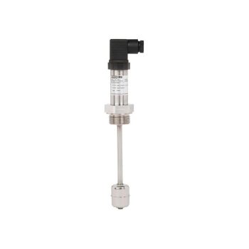
- Media compatibility: Oil, water, diesel, refrigerants and other liquids
- Permissible medium temperature range: -30 ... +120 °C [-22 ... +248 °F]
- Output signal: Resistance in a 3-wire potentiometer circuit, current output 4 ... 20 mA
- Measuring principle: Reed-chain technology
- Accuracy, resolution: 24 mm [0.9 in], 12 mm [0.5 in], 10 mm [0.4 in], 6 mm [0.2 in] oder 3 mm [0.1 in]
| Datasheet |
| User Manual |
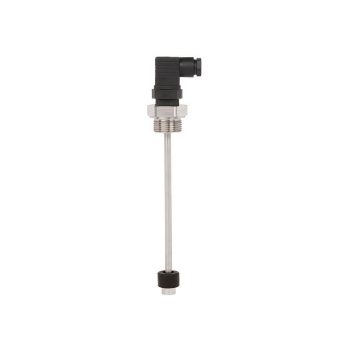
- Maximum reliability thanks to high-quality reed contacts
- Very high variety and customer-specific solutions possible
- Simple and fast installation
| Datasheet |
| User Manual |
- Lateral installation in the tank
- Operating limits:- Operating temperature: T = -40 ... +120 °C- Operating pressure: P = 5 bar - Limit density: ρ ≥800 kg/m3
- Plastic and stainless steel versions
- Space-saving installation
- Switch consists of only one component
| Datasheet |
| User Manual |
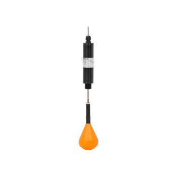
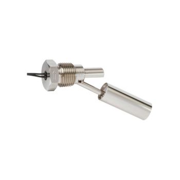
- Adjustable switch position through screw-adjustable float
- Switch rod actuator, potential-free reed switch
- Switch contact freely definable as normally closed, normally open or change-over contact
- Also reliable in strongly contaminated media
| Datasheet |
| User Manual |