


Petrochemistry
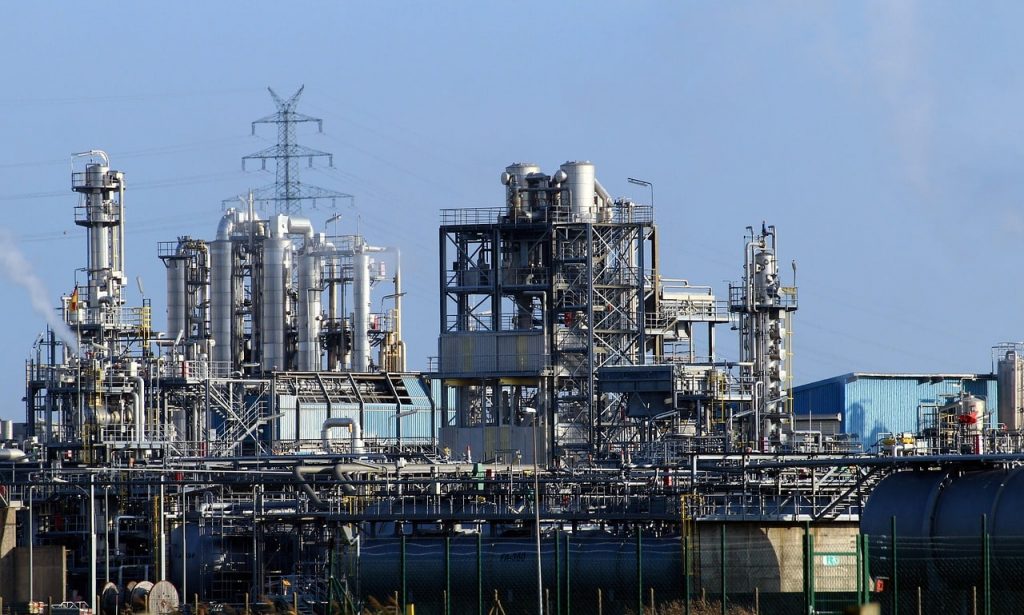
Petrochemistry is a fundamental and dynamic sector within the chemical industry, specializing in the transformation of fossil raw materials such as natural gas, shale gas, and naphtha into essential chemicals and intermediates. Core processes in this area include the production of ethylene and methanol, which serve as the basis for a wide range of derivatives. Through processes like thermal cracking, catalytic synthesis, and distillation, valuable intermediates such as butadiene, benzene, ethylene, and propylene are produced. These compounds are indispensable for the synthesis of plastics, solvents, synthetic fibers, and many other chemical products that play a central role in our daily lives.
Importance of Measurement and Monitoring Technologies
The success and efficiency of petrochemistry significantly depend on the accuracy and reliability of the measurement and monitoring technologies used. Instruments designed specifically for use in explosive and corrosive environments, such as ATEX-certified measuring devices, are crucial for safety. Furthermore, instruments certified according to Safety Integrity Level standards (SIL, according to IEC 61508), enhance plant reliability by minimizing the likelihood of operational disruptions and thus ensuring continuous production.
Advanced Safety Standards
To master the diverse challenges in petrochemistry, advanced safety standards are essential. Standards such as NACE / ISO 15156 have been developed specifically for requirements in environments with high hydrogen sulfide content (H2S) to prevent corrosion and thus ensure the longevity and reliability of the instrumentation. These standards are crucial for safe handling of highly reactive and potentially dangerous raw materials and products like butadiene, benzene, and ethylene.
Technical Solutions for Petrochemical Processes
Specific requirements of petrochemical processes, especially when dealing with aggressive media and at high operating temperatures, necessitate individually tailored technical solutions. These include diaphragm seal systems and protection tubes that help protect the measurement instrumentation from extreme conditions. Moreover, precise measuring devices for pressure, temperature, and level, as well as calibration services, are essential to ensure the accuracy and reliability of process control in refineries and chemical plants.
Application Examples
- Crack pyrolysis furnaces crucial for the production of ethylene, a key building block for plastics and other synthetic materials.
- Steam methane reformers that produce hydrogen and synthesis gas for ammonia synthesis and other chemical processes.
- Distillation columns that allow precise separation of monomers like propylene, needed for the production of polypropylene and other polymers.
- Polymerization reactors that form the basis for the production of a variety of plastics.
- Tube bundle reactors for the efficient oxidation of hydrocarbon compounds to gain important industrial chemicals.
- Tank farms that ensure the safe storage of chemicals and intermediates, thereby supporting a continuous supply chain.
These technologically advanced applications demonstrate the complexity and innovation potential of petrochemistry. Through continuous research and development, as well as the implementation of advanced safety and monitoring systems, petrochemistry significantly contributes to the economic development and sustainability of our modern society.
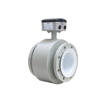
SITRANS FM MAG 3100 P Full-bore electromagnetic flow sensor, flanged, diameter DN 15 to DN 300 (1/2" to 12"). Suitable for volume flow measurement of liquids (conductive), main applications in chemical industry, process industry, pulp & paper, industrial wastewater.
![]()
 Datasheet Datasheet |
| User Manual |
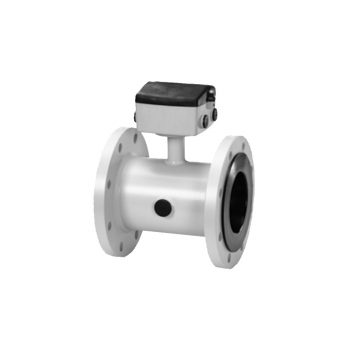
SITRANS FM MAG 5100 W Electromagnetic flow sensor, flanged, diameter DN 15 to DN 1200 (1/2" to 48"). Suitable for volume flow measurement of liquids (conductive) , for applications in water abstraction, water & wastewater treatment, water distribution networks, custody transfer metering.
| Datasheet |
| User Manual |
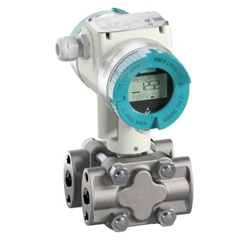
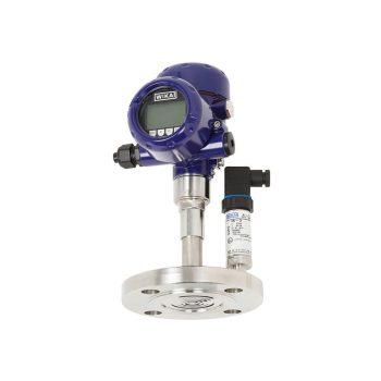
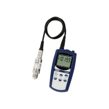
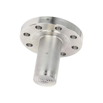
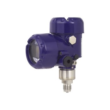
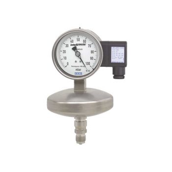
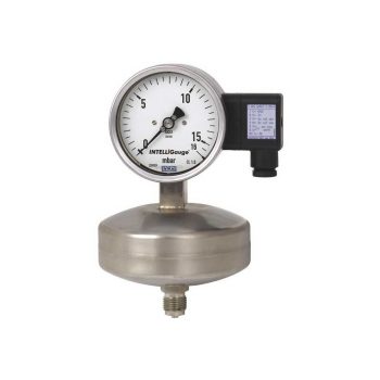
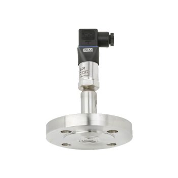
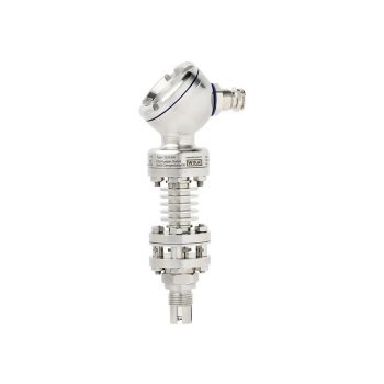
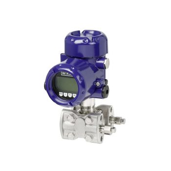
The digital pressure transmitter which features remote safety handling - developed according to IEC61508 standards for SIL2/3. Accuracy: 0,065 %
![]()
|
Datasheet
|
|
User Manual
|
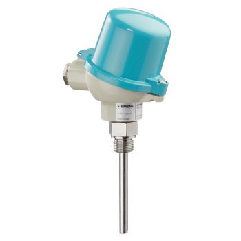
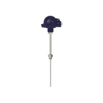
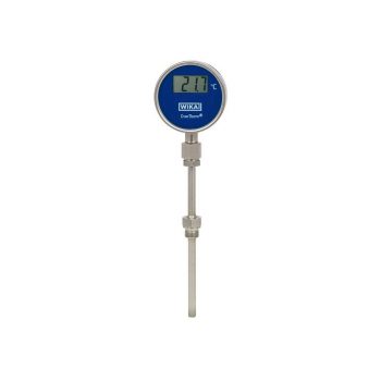
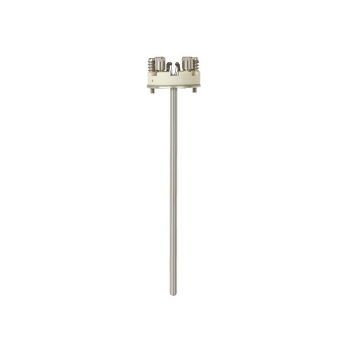
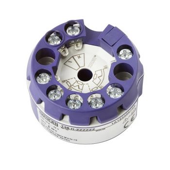
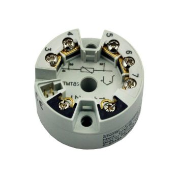
2-wire head transmitter with and without HART communications interface for mounting in the connection head of the temperature sensor.
|
Datasheet
|
|
User Manual
|
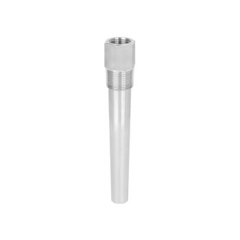
Tubular thermowell for low to medium stress, according to DIN 43722, Type 2, without process connection, without extension, plug-in or use with move-able compression fittings
![]()
|
Catalog Excerpt
|
|
User Manual
|
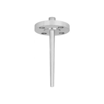
Tubular thermowell, low to medium stress, according to DIN 43722, Type 2F, with flange, with extension
![]()
|
Catalog Excerpt
|
|
User Manual
|

Thermometerschutzrohr aus Rohrmaterial, geringe bis mittlere Beanspruchung, nach DIN 43772, Typ 2G, verschraubte Ausführung, mit Verlängerung
![]()
|
Catalog Excerpt
|
|
User Manual
|
Tubular thermowell, low to medium stress, Type 2N similar to DIN 43722, screwed design, without extension, for maximum process temperatures of 100 °C
![]()
|
Catalog Excerpt
|
|
User Manual
|
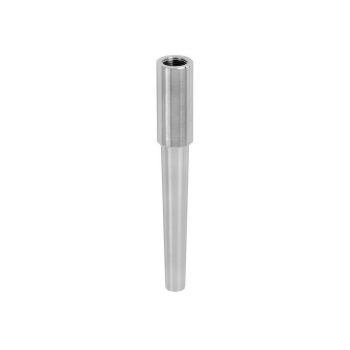
Tubular thermowell for low to medium stress, according to DIN 43722, Type 3, without process connection, improved response time, plug-in or use with moveable compression fittings
![]()
|
Catalog Excerpt
|
|
User Manual
|
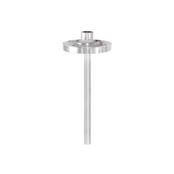
Tubular thermowell, low to medium stress, according to DIN 43722, Type 3F, with flange, with extension
![]()
|
Catalog Excerpt
|
|
User Manual
|
Tubular thermowell, low to medium stress, according to DIN 43722, Type 3G, screwed design, with extension
![]()
|
Catalog Excerpt
|
|
User Manual
|
Barstock thermowell for medium to extreme stress, according to DIN 43722, Type 4, for welding in, Type 4F with flange, with extension
![]()
|
Catalog Excerpt
|
|
User Manual
|
Temperature sensors for installation in existing thermowells, suitable for ther-mowells according to DIN 43772 as well as ASME B40.9-2001 with extension European or American types
![]()
|
Catalog Excerpt
|
|
User Manual
|
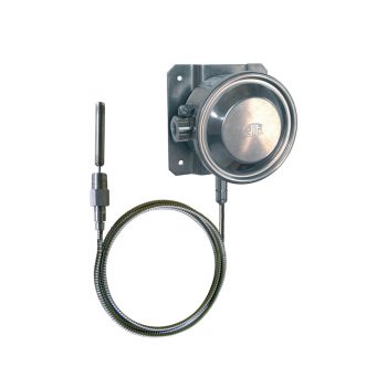
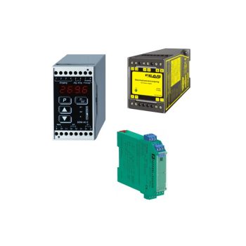
- TÜV zertifizierte SIL-Version für Schutzeinrichtungen entwickelt nach IEC 61508 (Option)
- Einsatz in Sicherheitsanwendungen bis SIL 2 (einzelnes Gerät) und SIL 3 (redundante Verschaltung)
- Konfigurierbar mit nahezu jedem offenen Soft- und Hardwaretool
- Universell für den Anschluss von 1 oder 2 Sensoren - Widerstandsthermometer, Widerstandssensor - Thermoelement, mV-Sensor - Potentiometer
- Signalisierung gemäß NAMUR NE43, Sensorbruchüberwachung gemäß NE89, EMV gemäß NE21

 Datenblatt Datenblatt |
| Bedienungsanleitung |
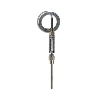
- Sensor ranges from -196 ... +600 °C (-320 ... +1.112 °F)
- For mounting in all standard thermowell designs
- Spring-loaded measuring insert (replaceable)
- Pt100 or Pt1000 sensors
- Explosion-protected versions
| Datasheet |
| User Manual |
| User Manual |
| User Manual |
| User Manual |
| User Manual |
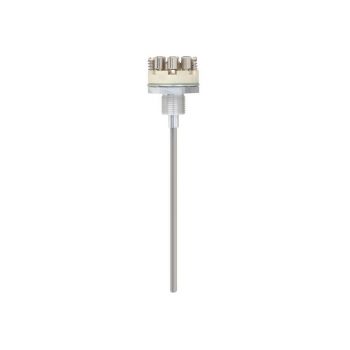
- Versions to customer specification
- Various process connections
- Short response times
- Robust, vibration-resistant design
- Various thermocouple types and electrical connection types
| Datasheet |
| Datasheet |
| User Manual |
| User Manual |
| User Manual |
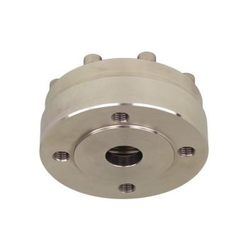
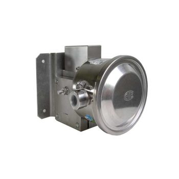
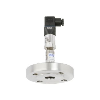
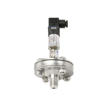
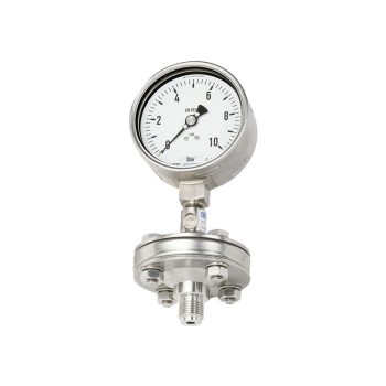
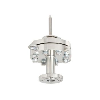
- Double-diaphragm system to ensure the separation of the process and the pressure measuring instrument
- Process connection with flange to provide for direct threaded connection
- All welded design with flush diaphragm
- Wetted parts from Hastelloy
| Datasheet |
| User Manual |
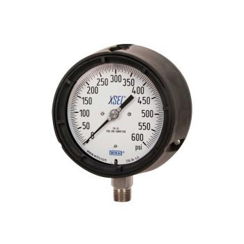
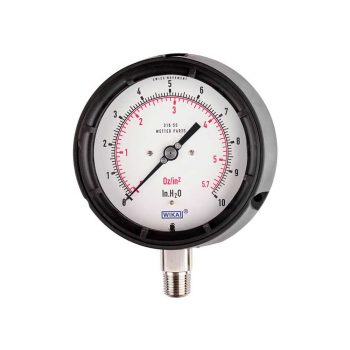
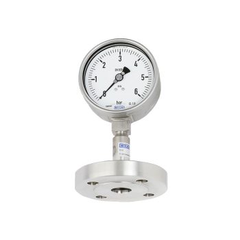
- Excellent load-cycle stability and shock resistance
- All stainless steel construction
- German Lloyd approva
- Scale ranges up to 0 … 1,600 bar
| Datasheet |
| User Manual |
| User Manual |
| User Manual |
| User Manual |
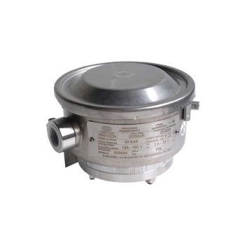
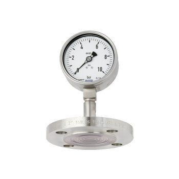
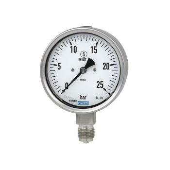
- Safety version with solid baffle wall designed in compliance with the requirements and test conditions of EN 837-1
- Excellent load-cycle stability and shock resistance
- Completely from stainless steel
- Scale ranges from 0 … 0.6 to 0 … 1,600 bar
|
Datasheet |
| User Manual |
| User Manual |
| User Manual |
| User Manual |
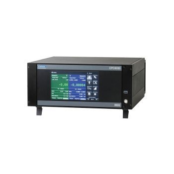
Model CPH6300-S1 (1-channel version) Model CPH6300-S2 (2-channel version)
|
Datasheet
|
|
User Manual
|
- Application ranges from -200 ... +600 °C [-328 ... +1,112 °F]
- Made of mineral-insulated sheathed cable
- Explosion-protected versions (option)
![]()
|
Datasheet
|
|
User Manual
|
|
User Manual
|
![]()
|
Datasheet
|
|
User Manual
|
- Total measurement uncertainty up to 0.025 % of reading
- Upgradeable using CPS5800/CPM5800 to provide increased accuracy to 0.006 %
- Direct replacement of original DH-Budenberg 580 series
- Factory calibration included as standard, traceable to national standards, with UKAS calibration possible as an option
- Masses manufactured from stainless steel, can be adjusted to local gravity
|
Datasheet
|
|
User Manual
|
- Cost-effective “2 in 1” temperature measurement
- Compact design
- Application ranges from -200 ... +700 °C
- “Plug-and-play”, thus no transmitter configuration necessary
![]()
|
Datasheet
|
|
User Manual
|
- For many variants of temperature transmitters including field transmitter
- For mounting in all standard thermowell designs
- Spring-loaded measuring insert (replaceable)
- Explosion-protected versions (option)
![]()
|
Datasheet
|
|
User Manual
|
|
User Manual
|
|
User Manual
|
|
User Manual
|
- Application ranges up to max. 1,600 °C / 2,912 °F (DIN EN 50446)
- Thermowell made of heat-resistant steel or ceramic, also with ceramic inner tube
- Support tube of carbon steel
- Gastight process connection
- Coating (optional)
|
Datasheet
|
|
User Manual
|
|
User Manual
|
- Application ranges from -40 ... +1,200 °C (-40 ... +2,192 °F)
- For many variants of temperature transmitters including field transmitter
- For mounting in all standard thermowell designs
- Spring-loaded measuring insert (replaceable)
- Explosion-protected versions
| Datasheet |
| User Manual |
| User Manual |
| User Manual |
Special Features
- Total measurement uncertainty to 0.006 % of reading
- Extremely flexible instrument with a wide range of single and dual-range piston-cylinder systems
- Dual-range piston-cylinder systems with fully automated changing between ranges
- Factory calibration includes traceability to national standards, as standard, with UKAS calibration possible as an option
- Fast and safe replacement of the piston-cylinder system via patented ConTect quick-release system as an option
|
Datasheet
|
|
User Manual
|
- Scale ranges from -200 ... +700 °C [-328 ... 1.292 °F]
- Fast response behaviour
- Case and stem from stainless steel
- Various connection and case mounting designs
| Datasheet |
| User Manual |
- Installation of head-mounted transmitters in the connection housing possible
- Wide variety of different electrical connections, process connections, materials and contact separations
- Programmable and configurable head-mounted transmitters for 4 ... 20 mA, HART®, PROFIBUS® PA or FOUNDATION™ Fieldbus field signals
- Explosion-protected versions
- Temperature ranges from -100 … +350 °C

| Datenblatt |
| Datenblatt |
| Datenblatt |
| Bedienungsanleitung |
| Bedienungsanleitung |
| Bedienungsanleitung |
- Patent applied for, among others DE Patent No. 102013215351
- New calibration concept simplifies certificate generation
- Easy operation and set up
- Acquisition and automatic correction of all critical influencing factors, to increase the accuracy of the measurement
- Can also be used with other calibration instruments and WIKA-Cal software
|
Datasheet
|
|
User Manual
|
- Total measurement uncertainty starting from 0.015 ... 0.006 % of reading
- Four different piston-cylinder systems available for ranges ±1 bar, 0.1 ... 7 bar, 0.2 ... 25 bar, 1 ... 70 bar and 1 ... 120 bar, or also for ranges in lb/in² and kPa
- Stable aluminium base with a strong impact-resistant ABS cover for heavy industrial use combined with compact dimensions and light weight
- Interchangeable pistons and mass sets for each model, mass sets manufactured from stainless steel
- Factory calibration includes traceability to national standards, as standard; with UKAS calibration possible as an option
|
Datasheet
|
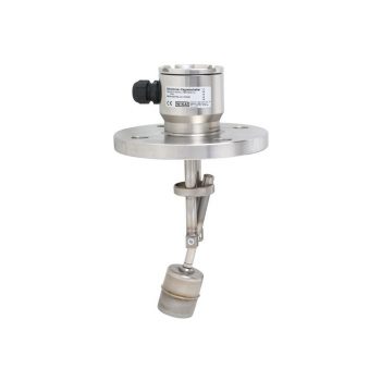
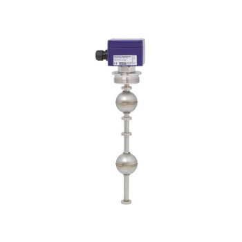
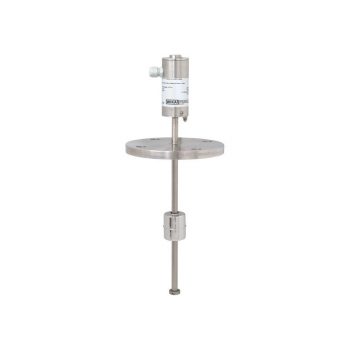
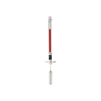
- Continuous level measurement on the outside of the bypass
- 2-wire technology 4 ... 20 mA
- Measured value output via digital interface and a selectable measured value as analogue signal
- Case from stainless steel (display from glass)
- Magnetostrictive level measuring instrument with high resolution
| Datasheet |
| User Manual |
| User Manual |
| User Manual |

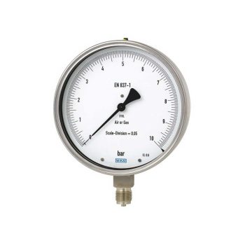
- Suitable for liquid, gas and steam flow measurement
- Accuracy ≤ ±0.5 % of actual flow rate
- Repeatability of measurement 0.1 %
- Lowest pressure loss in the family of primary flow elements
- Calibration may be performed if required
| Datasheet |
| User Manual |
- Process- and procedure-specific production
- Operating limits: - Operating temperature: T = -196 ... +450 °C - Operating pressure: P = Vacuum up to 400 bar
- Wide variety of different process connections and materials
- Mounting of level sensors and guided wave radars possible as an option
| Datasheet |
| User Manual |
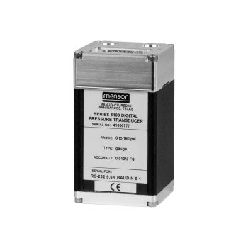
- Accuracy: 0.020 % FS
- Measuring range: 25 mbar ... 1,001 bar [10 inH2O ... 15,015 psi]
- Temperature compensation: 0 ... 50 °C [32 ... 122 °F]
- RS-232 or RS-485 communication
- Rugged and compact design
|
Datasheet
|
|
User Manual
|
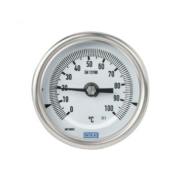
- Nominal sizes 63, 80, 100, 160 mm
- Robust, hermetically sealed case
- External reset for setting the reference temperature
- Dished dial (anti-parallax) for ease of reading
- Adjustable stem and dial version enables optimal process connection
|
Datasheet
|
|
User Manual
|
- Compact and space-saving design
- Output signal 4 ... 20 mA (NAMUR NE43) or HART® ver. 6
- Operating limits: - Operating temperature: T = -40 ... +250 °C - Operating pressure: P = Vacuum to 40 bar - Limit density: ρ ≥ 580 kg/m3
- Explosion-protected version (option)
- Vibration resistant version (option)
| Datenblatt |
| Bedienungsanleitung |
| Bedienungsanleitung |
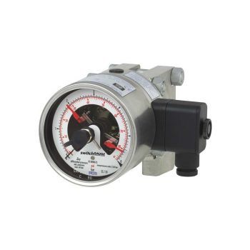
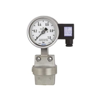
Switch contacts (electrical alarm contacts) make or break circuits dependent upon the pointer position of the indicating measuring instruments.
|
Datasheet |
| User Manual (Pressure gauges with inductive contact) |
| User Manual (Pressure gauges switch contact model) |
| User Manual (Pressure gauges with Reed contact) |
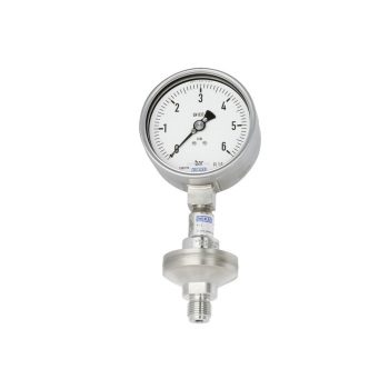
- Excellent load-cycle stability and shock resistance
- Safety version with solid baffle wall designed in compliance with the requirements and test conditions of ASME B 40.100
- With case filling (model 233.34) for applications with high dynamic pressure loads and vibrations
- Scale ranges from 0 … 10 to 0 … 30,000 psi [0 ... 0.6 to 0 ... 2,000 bar]
|
Datasheet |
| User Manual |
- Overpressure range is indicated completely on scale
- Safety version with solid baffle wall (Solidfront) designed in compliance with the requirements of EN 837-1 and ASME B40.100
- With case filling (model 233.36) for applications with high dynamic pressure loads and vibrations
- Measuring ranges from 0 … 0.6 bis 0 … 40 bar [0 ... 10 to 0 ...600 psi]
|
Datasheet |
| User Manual |
| User Manual |
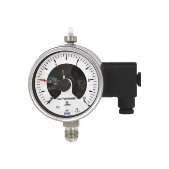
- Up to 4 switch contacts per instrument
- Also available with case filling for high dynamic pressure loads or vibrations
- Instruments with inductive contacts for use in hazardous areas
- Instruments with contacts for PLC applications
- Instruments optionally available in safety version S3 per EN 837
| Datasheet |
| User Manual |
| User Manual |
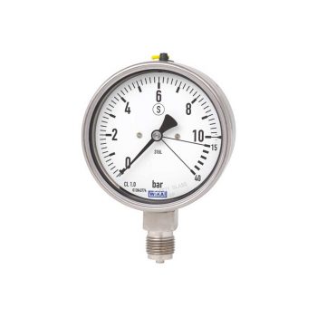
- Safety pressure gauge with solid baffle wall designed in compliance with the requirements and test conditions of EN 837-1
- Completely from stainless steel
- Knife edge pointer for optimal accuracy of reading
- Wear-resistant precision movement from stainless steel
- Scale ranges from 0 … 0.6 to 0 … 1,600 bar [0 ... 10 psi to 0 ... 20,000 psi]
| Datasheet |
| User Manual |
| User Manual |
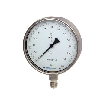
- Completely from stainless steel
- Knife edge pointer for optimal accuracy of reading
- Wear-resistant precision movement from stainless steel
- Scale ranges from 0 … 0.6 to 0 … 1,600 bar [0 ... 10 psi to 0 ... 20,000 psi]
|
Datasheet |
| User Manual |
| User Manual |
- Compatible with switch contacts
- Threaded or open flange process connection
- Scale ranges from 0 … 16 mbar
| Datasheet |
| User Manual |
- High overload safety, optionally up to 40, 100 or 400 bar, due to the metallic pressure element limit stop, without liquid-filled measuring cell
- Wide choice of special materials
- Also available with liquid-filled case for high dynamic pressure loads or vibrations
- Instruments with inductive contacts for use in hazardous areas
- Instruments with switch contact for PLC applications
|
Datasheet |
| User Manual |
| User Manual |
- Case and wetted parts from stainless steel
- Wide choice of special materials
- High overload safety up to the 10-fold full scale value
- Process connection thread or open flange
- Scale ranges from 0 … 16 mbar
|
Datasheet |
| User Manual |
| User Manual |
| User Manual |
- Differential pressure measuring ranges from 0 … 16 mbar
- High working pressure (static pressure) and high overload safety up to 40 bar
- Also available with liquid-filled case for high dynamic pressure loads or vibrations
- Instruments with inductive contacts for use in hazardous areas
- Instruments with switch contact for PLC applications
|
Datasheet |
| User Manual |
| User Manual |
- Robust, hermetically sealed case
- Accuracy: ±1 % of full scale value ASME B40.200 (grade A)
- External reset for reference temperature adjustment
- Dished dial (anti-parallax) for ease of reading
- Adjustable stem and dial version enables optimal process connection
| Datasheet |
| User Manual |
- High overload safety
- Long service life due to metal media chamber sealing and the extremely gas-tight material of the reference chamber
- Instruments compatible with switch contacts
- Scale ranges from 0 … 25 mbar absolute pressure
| Datasheet |
| User Manual |
| User Manual |
- Scale ranges from -70 ... +600 °C
- For extreme ambient temperatures
- Maintenance-friendly bayonet case
- All stainless steel construction
- Individual stem length from 63 ... 1,000 mm
![]()
|
Datasheet
|
|
User Manual
|
|
User Manual
|
- Zero point correction in front
- Completely from stainless steel
- With liquid-filled case for applications with high dynamic pressure loads and vibrations (model 633.50)
- Low scale ranges from 0 ... 2.5 mbar to 0 ... 600 mbar or 0 ... 1 inH2O to 0 ... 240 inH2O
| Datasheet |
| User Manual |
| User Manual |
- High overload safety up to 50 x full scale value
- Scale ranges from 0 … 2.5 mbar
- Measuring chamber protected against unauthorised intervention
- Low measuring error and influence on function from medium pollution
| Datasheet |
| User Manual |
| User Manual |
- High overload safety up to 50 x full scale value
- High reliability and long service life
- Up to 4 switch contacts per instrument
- Instruments with inductive contacts for use in hazardous areas
- Instruments with switch contact for PLC applications
| Datasheet |
| User Manual |
| User Manual |
- Differential pressure measuring ranges from 0 ... 16 mbar to 0 ... 40 bar or 0 ...10 inH2O to 0 ... 600 psi
- High operating pressure (static pressure) up to 40 bar [600 psi]
- High overload safety up to 40 bar [600 psi]
- Models 732.31 and 733.31: Case with safety level “S3” per EN 837
- All-welded media chamber
| Datasheet |
| User Manual |
| User Manual |
- Differential pressure measuring ranges from -1 … +30 bar [-14.5 ... 435 psi] to 0 ... 40 bar [0 ... 580 psi]
- High working pressure (static pressure) and high overload safety, selectable 40 bar [580 psi], 100 bar [1,450 psi], 250 bar [3,625 psi], 400 bar [5,800 psi] and 650 bar [9,425 psi]
- The transmission fluid in the measuring chamber dampens the indicator in case of high changes of the rate of pressure
- Model 73x.14: Stainless steel version
- Model 76x.14: Version with special materials
| Datasheet |
| User Manual |
| User Manual |
- Differential pressure measuring ranges from 0 … 60 mbar
- High working pressure (static pressure) and high overload safety, selectable up to 40, 100, 250 or 400 bar
- Measuring cell liquid dampening against rapid pressure changes
- Instruments with inductive contacts for use in hazardous areas
- Instruments with switch contact for PLC applications
|
Datasheet |
| User Manual |
| User Manual |
- Simple mounting of the illumination system
- Illumination types available for different applications
- Operating temperature: depending on illumination method
- Matching to the respective length of the glass indicator
| Datasheet |
| User Manual |
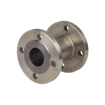
- Completely round, no corners and edges
- For direct installation between two flanges
- Wide choice of special materials
| Datasheet |
| User Manual |
- Completely round, no corners and edges
- For direct installation between two flanges
- Wide choice of special materials
| Datasheet |
| User Manual |
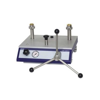
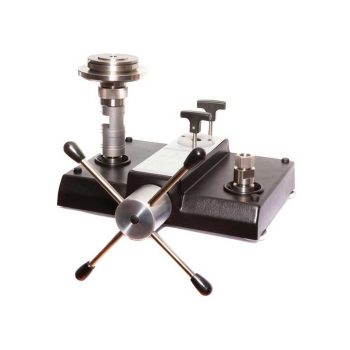
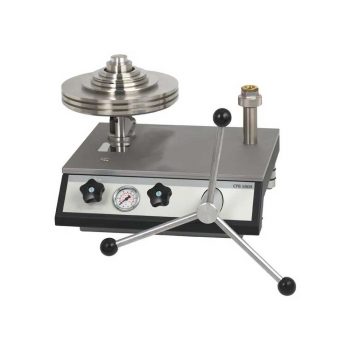
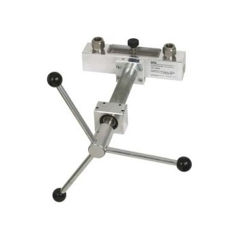
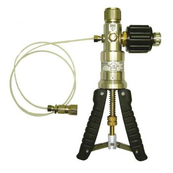
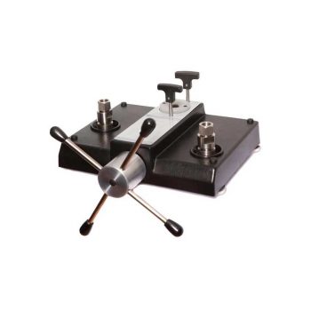
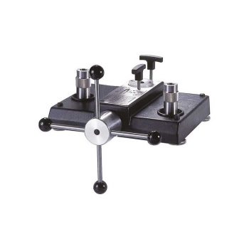
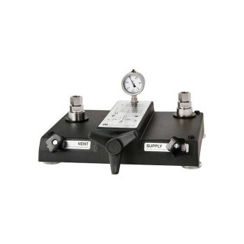
- Ergonomic handling through the smooth-running, internally operating, precision spindle
- Integrated oil reservoir
- Removable star handle
- Freely rotating test connections (i.e. measuring instruments can be aligned)
- Integrated priming pump for large test volumes
|
Datasheet
|
|
User Manual
|
- Process connection with thread
- Version with internal diaphragm, diaphragm seal parts screwed together
- Large selection of process connections and materials
- Flushing connections optionally available
| Datasheet |
| User Manual |
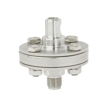
- Flange with internal welded diaphragm
- Mounting to measuring instruments for low pressures, also for differential pressure
- Flushing connections optionally available
| Datasheet |
| User Manual |
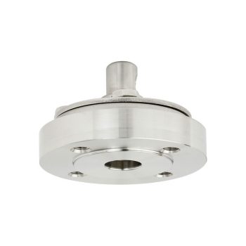
- Flush diaphragm
- Process connection to provide for direct threaded connection with block flange or saddle flange
| Datasheet |
| User Manual |
- Flange with flush welded diaphragm
- Common standards and nominal widths available
- Wide variety of different materials and material combinations
| Datasheet |
| User Manual |
- Compact cell-type
- Intermediate flange with flush diaphragm
- Common standards and nominal widths available
- Wide variety of different materials and material combinations
- Instrument connection via radial gauge adapter
| Datasheet |
| User Manual |
- High pressures up to PN 400 / class 2.500
- Flange with internal welded diaphragm
- Small process connections
- Flushing connections optionally available
| Datasheet |
| User Manual |
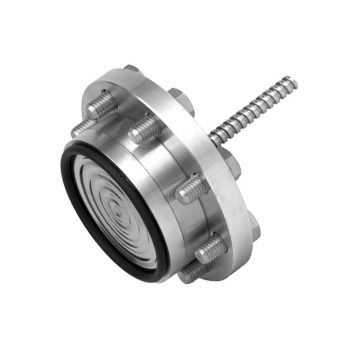
- Flange with extended welded diaphragm
- Common standards and nominal widths available
- When special materials are selected, all wetted parts are made of the selected material
- Robust, all welded design
| Datasheet |
| User Manual |
- Process connection with thread
- Version with internal diaphragm, diaphragm seal parts fully welded
- Large selection of process connections and materials
- Flushing connections optionally available
- High pressures up to 1,000 bar [14,500 psi] can be achieved
| Datasheet |
| User Manual |
- Intermediate flange (diaphragm seal cell) with extended diaphragm
- Versions for all common standards and nominal widths available
- When special materials are selected, all wetted parts are made of the selected material
| Datasheet |
| User Manual |
- Threaded connection for screwing in directly
- Flush diaphragm with compact dimensions
- High pressures for the process industry
- Version with protective plate for increased wear resistance
- Vacuum measuring ranges
| Datasheet |
| User Manual |
- Internal diaphragm with large working volume
- Special materials available
- Low temperature error due to large diaphragm diameter (realisation of low measuring ranges possible)
- Wide temperature application range due to large working volume
- Integrated flushing connections (optional)
| Datasheet |
| User Manual |
- Total measurement uncertainty to 0.008 % of reading
- Factory calibration included as standard, traceable to national standards; with DKD/DAkkS calibration possible as an option
- High long-term stability with recommended recalibration interval every five years
- Masses manufactured from stainless steel and aluminium, can be adjusted to local gravity
- Quick and safe replacement of the piston-cylinder system for measuring range changes via patented ConTect quickrelease system as an option
|
Datasheet
|
|
Bedienungsanleitung
|
![]()
|
Datasheet
|
|
User Manual
|
|
User Manual
|
|
User Manual
|
|
User Manual
|
|
Datasheet
|
|
User Manual
|
- Good price/performance ratio
- Wetted parts made of special material
- Non-wetted flange from 316/316L stainless steel
- Thermowell welded to one unit
- Possible thermowell forms: - tapered, straight or stepped - "Quill Tip" version (with open tip)
|
Datasheet (Model TW10-P)
|
|
Datasheet (Model TW10-F, Models TW10-P and TW10-R)
|
|
Datasheet (ScrutonWell® design)
|
|
User Manual
|
- Connection between flange and thermowell in threadwelded design
- Model TW10-S: No directly wetted welded joints (standard)
- Model TW10-B: Additional weld seam on the process side (sealing joint)
- Coating for corrosive or abrasive process loads
- Possible thermowell forms: - tapered, straight or stepped - “Quill Tip” version (with open tip)
|
Datasheet (Models TW10-S, TW10-B)
|
|
Datasheet (ScrutonWell® design)
|
|
User Manual
|
- International standard
- Possible thermowell forms: - tapered, straight or stepped - "Quill Tip" version (with open tip)
|
Datasheet
|
|
User Manual
|
- Different dimensions for standardised welding sockets
- International standard
- Possible thermowell forms: - Design TW20-A: tapered - Design TW20-B: straight - Design TW20-C: stepped - “Quill Tip” version (with open tip)
|
Datasheet
|
|
User Manual
|
- Variable welding diameters
- International standard
- Possible thermowell forms: - Design TW25-A: tapered - Design TW25-B: straight - Design TW25-C: stepped - "Quill Tip" version (with open tip)
|
Datasheet
|
|
User Manual
|
- Heavy-duty design
- Solid machined version without welding
- Possible thermowell forms: Design TW30-A: tapered Design TW30-B: straight Design TW30-C: stepped
- For lap flanges per ASME B16.5
|
Datasheet
|
|
User Manual
|
- Pressure ranges: from 0 ... 25 mbar up to 0 ... 2,890 bar [0 ... 0.36 up to 0 ... 42,000 psi]
- Accuracy down to 0.008 % of IS (IntelliScale)
- External pressure ranges from 25 mbar ... 1,000 bar [0.36 ... 15,015 psi]
- Precision 0.004 % FS
- Removable/interchangeable sensors
|
Datasheet
|
|
User Manual
|
- Ergonomic handling through the smooth-running, internally operating, precision spindle
- Integrated oil reservoir
- Removable star handle
- Freely rotating test connections (i.e. measuring instruments can be aligned)
- Integrated priming pump for large test volumes
|
Datenblatt
|
|
Bedienungsanleitung
|
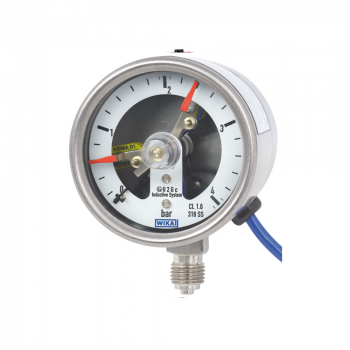
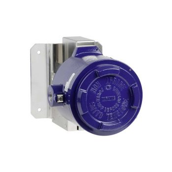
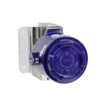
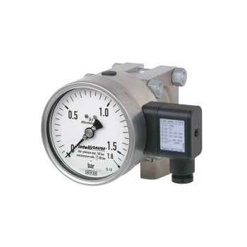
- Electropolished case
- Ingress protection IP 65, NEMA 4
- Ambient temperature -40 ... +85 °C
- 1 or 2 independent switch points, high contact rating up to 15 A / AC 220 V
- Directly connected or via capillary (up to 10 m capillary)
![]()
![]()
|
Datasheet
|
|
User Manual
|
- Case from AISI 316 (1.4401)
- Ingress protection IP 66, NEMA 4
- Ambient temperature -40 ... +85 °C
- 1 switch point, SPDT, up to 5 A/AC 220 V
- Directly connected or via capillary (up to 10 m capillary
![]()
|
Datasheet
|
|
User Manual
|
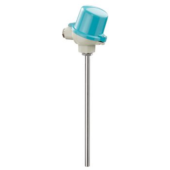
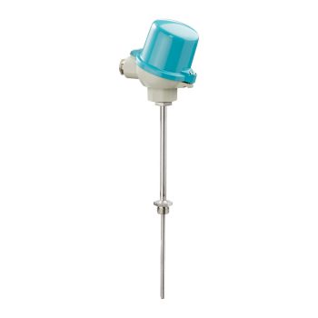
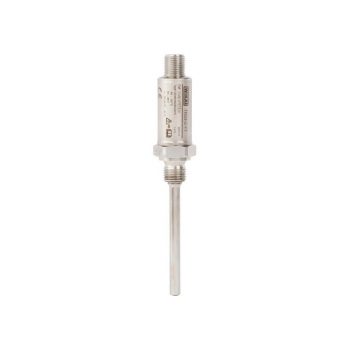
- Sensor ranges from -40 ... +1,200 °C (-40 ... +2,192 °F)
- Made of mineral-insulated sheathed measuring cable
- For all standard thermowell designs
- Spring-loaded design
- Explosion-protected versions
![]()
|
Datasheet
|
|
User Manual
|
|
User Manual
|
|
User Manual
|
- Ergonomic handling through the smooth-running, internally operating, precision spindle
- Integrated oil reservoir
- Removable star handle
- Freely rotating test connections (i.e. measuring instruments can be aligned)
- Precise setting of the test pressure through a fine adjustment valve (optional for model CPP1000-M)
|
Datasheet
|
|
User Manual
|
- Ergonomische Handhabung
- Präzise Einstellung durch Feinregulierventil
- Kompakte Abmessungen
- Geringes Gewicht
|
Datenblatt
|
|
Bedienungsanleitung
|
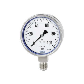
- Safety version with solid baffle wall designed in compliance with the requirements and test conditions of ASME B 40.100
- Low scale ranges from 0 ... 25 mbar to 0 ... 600 mbar
- Nominal size 4 ½" (115 mm)
- Robust, glass-fibre reinforced case from POCAN®
| Datasheet |
| User Manual |
- No power supply needed for switching of electrical loads
- Robust switch enclosure from aluminium, IP66, NEMA 4X
- Setting ranges from 0 ... 25 mbar abs. to 0 ... 1.5 bar abs.
- Repeatability: ≤ 1 % of span
- 1 or 2 independent set points, SPDT or DPDT, high switching power up to AC 250 V, 20 A
| Datasheet |
| User Manual |
- No configuration necessary due to “plug-and-play”
- Scale ranges from 0 … 25 mbar absolute pressure
- Easy-to-read analogue display with nominal sizes 100 and 160
- High overload safety, long service life due to metallic media chamber sealing
- Media chamber protected against unauthorised access
| Datasheet |
| User Manual |
- Accuracy up to 0.1 K (complete measuring chain)
- One- and two-channel versions
- Connection possibilities for various probe types
- Intrinsically safe version Ex ib IIB T4 Gb
![]()
| Datasheet |
| User Manual |
| User Manual |
- No power supply needed for switching of electrical loads
- Robust switch enclosure from 316L, IP66/NEMA 4X
- Setting ranges from 0 ... 25 mbar abs. up to 0 ... 1.5 bar abs.
- Intrinsic safety Ex ia available
- 1 or 2 independent set points, SPDT or DPDT, high switching power up to AC 250 V, 20 A
| Datasheet |
| User Manual |
- No power supply needed for switching of electrical loads
- Robust switch enclosure from aluminium, IP 66, NEMA 4X
- Setting ranges from 0 ... 2.5 bar up to 0 ... 1,000 bar, vacuum ranges
- Repeatability of the set point ≤ 0.5% of span
- 1 or 2 independent set points, SPDT or DPDT, high switching power up to AC 250 V, 20 A
| Datasheet |
| User Manual |
- No power supply needed for switching of electrical loads
- Robust switch enclosure from aluminium alloy, IP66, NEMA 4X
- Setting ranges from 0 ... 16 mbar to 0 ... 40 bar with high static and high one-sided pressure up to 160 bar
- Repeatability: ≤ 1 % of span
- 1 or 2 independent set points, SPDT or DPDT, high switching power up to AC 250 V, 20 A
| Datasheet |
| User Manual |
- No power supply needed for switching of electrical loads
- Robust switch enclosure from aluminium alloy or stainless steel 316L, IP66, NEMA 4X
- Setting ranges from 0 ... 160 mbar to 0 ... 40 bar with high static and high one-sided pressure up to 250 bar
- Intrinsic safety Ex ia available
- 1 set point, SPDT or DPDT, high switching power up to AC 250 V, 15 A
| Datasheet |
| User Manual |
- Precisely adjustable dual-area spindle pump for filling, pressure generation and fine adjustment of pressure
- Freely rotating test connections (i.e. measuring instruments can be orientated)
- Proven technology of the model CPB3800 pressure balance
- Compact dimensions
- Low weight
| Datasheet |
| User Manual |
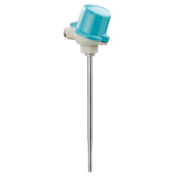
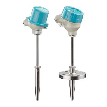
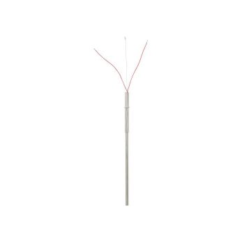
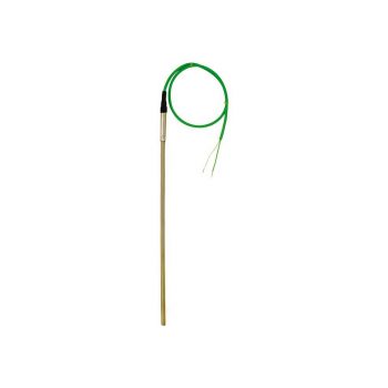
- Sensor ranges from -196 ... +600 °C [-320 ... +1,112 °F]
- Made of mineral-insulated sheathed measuring cable
- For all standard thermowell designs
- Spring-loaded design
- Explosion-protected versions are available for many approval types (see data sheet page 2)
![]()
|
Datasheet
|
|
User Manual
|
|
User Manual
|
|
User Manual
|
|
User Manual
|
|
User Manual
|
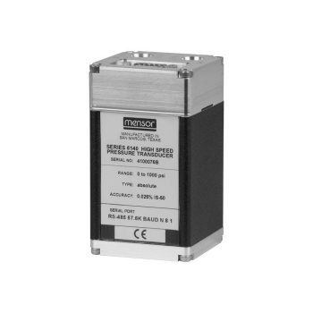
- Accuracy up to 0.025 % IS-50
- Measuring range from -1 ... +400 bar (-15 ... +6,000 psi)
- Output mode 250 Hz (4 ms) response time
- Streaming output mode in IEEE-754 format
|
Datasheet
|
|
User Manual
|
- Sensor ranges from -40 ... +1,200 °C (-40 ... +2,192 °F)
- Measuring insert replaceable
- For many thermowell designs
![]()
|
Datasheet
|
|
User Manual
|
|
User Manual
|
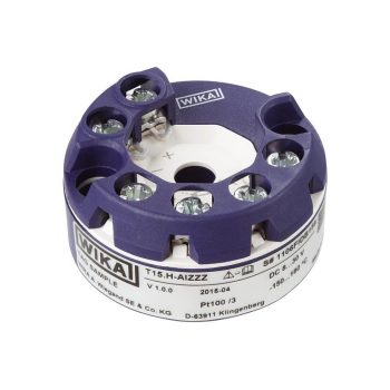
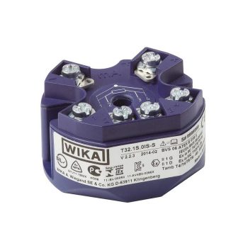
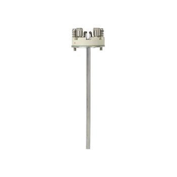
- For the connection of Pt100 and Pt1000 sensors in a 2-, 3- or 4-wire connection
- For the connection of reed chains in a potentiometer circuit
- Parameterisation with the WIKAsoft-TT configuration software and electrical connection via quick connector magWIK
- Connection terminals also accessible from the outside
- Accuracy < 0.2 K (< 0,36 °F) / 0.1 %
| Datasheet |
| User Manual |
- No power supply needed for switching of electrical loads
- Robust switch enclosure from 316L, IP 66, NEMA 4X
- Setting ranges from 0 ... 2.5 bar up to 0 ... 1,000 bar, vacuum ranges
- Ex ia version available
- 1 or 2 independent set points, SPDT or DPDT, high switching power up to AC 250 V, 20 A
| Datasheet |
| User Manual |
- Pressure ranges: -1 ... 210 bar (-15 ... 3,045 psi)
- Control speed 10 s
- Control stability < 0.005 % FS
- Accuracy to 0.02 % IS (IntelliScale)
- Precision 0.008 % FS
|
Datasheet
|
|
User Manual
|
- Freely selectable switch position through fixing the float switch at the required level
- Large range of application due to the simple, proven functional principle
- For harsh operating conditions, long service life
- Operating limits: - Operating temperature: T = -30 ... +150 °C - Operating pressure: P = Vacuum up to 40 bar - Limit density: ρ ≥600 kg/m3
| Datasheet |
| User Manual |
- Application ranges from 0 ... 1,200 °C (32 ... 2,192 °F)
- Made of mineral-insulated sheathed cable
- Explosion-protected versions
![]()
|
Datasheet
|
|
User Manual
|
|
User Manual
|
![]()
|
Datasheet
|
|
User Manual
|
|
Datasheet
|
|
User Manual
|
- Pressure ranges: -1 ... 210 bar (-15 ... 3,045 psi)
- Control speed 15 s
- Control stability < 0.003 % FS (typical 0.001 % FS)
- Accuracy down to 0.01 % IS (IntelliScale)
- Precision 0.004 % FS
|
Datasheet
|
|
User Manual
|
- No power supply needed for switching of electrical loads
- Robust switch enclosure from stainless steel 316L, IP66, NEMA 4X
- Setting ranges from 0.3 ... 2.5 mbar to 0.7 ... 16 mbar with high working pressure and high static pressure up to 300 mbar
- Intrinsic safety Ex ia available
- 1 set point, SPDT, high switching power up to AC 250 V, 10 A
| Datasheet |
| User Manual |
- No configuration necessary due to “plug-and-play”
- Signal transmission per NAMUR
- Differential pressure measuring ranges from 0 … 16 mbar
- Easy-to-read analogue display with nominal sizes 100 and 160
- Individual, non-linear characteristic curves (e. g. x2 or √x for flow measurement)
| Datasheet |
| User Manual |
- Large range of application due to the simple, proven functional principle
- For harsh operating conditions, long service life
- Operating limits: - Operating temperature: T = -120 ... +350 °C - Operating pressure: P = Vacuum to 232 bar - Limit density: ρ ≥ 500 kg/m3
- Stainless steel and plastic versions
- Explosion-protected versions
| Datasheet |
| User Manual |
| User Manual |
| User Manual |
- High working pressure (static pressure) and high overload safety, selectable up to 40, 100, 250 or 400 bar
- Measuring cell liquid dampening against rapid pressure changes
- No configuration necessary due to "plug-and-play"
- Differential pressure measuring ranges from 0 … 60 mbar
- Individual, non-linear characteristic curves (e.g. x2 or √x for flow measurement)
| Datasheet |
| User Manual |
- Accuracy up to 0.01 % IS-50
- Measuring range from -1 ... 400 bar (-15 ... 6,000 psi)
- RS-232 or RS-485 interface
- Compact design
|
Datasheet
|
|
User Manual
|
- No power supply needed for switching of electrical loads
- Robust switch enclosure from stainless steel 316L, IP66, NEMA 4X
- Setting ranges from 0 ... 16 mbar to 0 ... 40 bar with high static and high one-sided pressure up to 160 bar
- Intrinsic safety Ex ia available
- 1 or 2 independent set points, SPDT or DPDT, high switching power up to AC 250 V, 20 A
| Datasheet |
| User Manual |
- Large range of application due to the simple, proven functional principle
- For harsh operating conditions, long service life
- Operating limits: - Operating temperature: T = -50 ... +350 °C - Operating pressure: P = Vacuum up to 40 bar - Limit density: ρ ≥ 300 kg/m3
- Wide variety of different electrical connections, process connections and materials
- Explosion-protected versions
| Datasheet |
| Datasheet |
| User Manual |
| User Manual |
| User Manual |
- Process- and procedure-specific production
- Operating limits: - Operating temperature: -196 ... +374 °C 1) - Operating pressure: Vacuum to 250 bar 1)
- Wide variety of different process connections and materials
- Illumination optional
- Heating and/or insulation optional
| Datasheet |
| User Manual |
| User Manual |
![]()
|
Datasheet
|
|
User Manual
|
|
User Manual
|
|
User Manual
|
|
User Manual
|
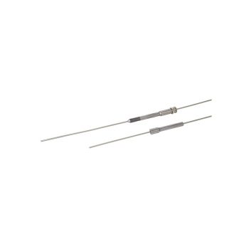
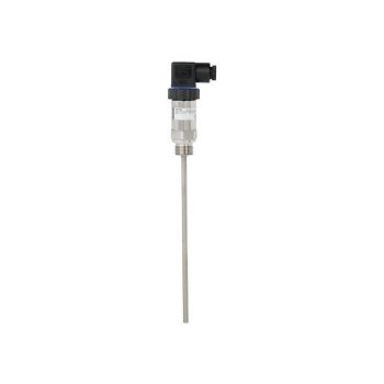
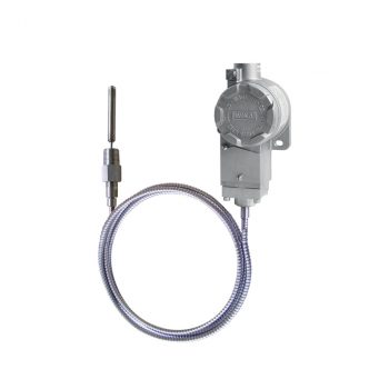
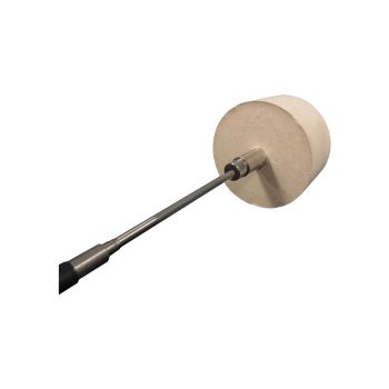
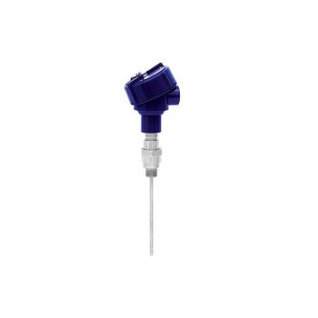
WIKA Model TC81 Thermocouple for flue gas temperature measurements – With protection tube model TW81
- Application ranges up to +1,200 °C (+2,192 °F)
- Protection tube from heat-resistant steel
- Measuring insert replaceable
- Gas-tight process connection (option)
|
Datasheet
|
|
User Manual
|
|
User Manual
|
|
User Manual
|
- Versions to customer specification
- Various process connections
- Exchangeable measuring inserts
- Application in conjunction with a thermowell
- Explosion-protected versions Ex i, Ex n and NAMUR NE24
| Datasheet |
| User Manual |
| User Manual |
| User Manual |
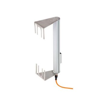
- Proper functioning, even under extreme environmental influences, e.g. dirt, humidity, gases, dust, chips
- Compact and operationally safe design
- Mounting of the switches at the magnetic display with T-slot or with tightening strap
- Process temperature of -60 ... +380 °C (depending on version)
| Datasheet |
| Datasheet |
| User Manual |
| User Manual |
| User Manual |
- Sealed, pressure retaining design
- Density range from 340 kg/m³
- Pressures up to 400 bar
- Medium temperatures from -196 ... +450 °C
- Versions for interface layer
| Datasheet |
| User Manual |
- Process- and system-specific solutions possible
- Operating limits: - Operating temperature: T = -80 ... +200 °C - Operating pressure: P = Vacuum up to 80 bar - Limit density: ρ ≥400 kg/m3
- Wide variety of different electrical connections, process connections and materials
- Optionally with programmable and configurable head-mounted transmitter for 4 ... 20 mA field signals, HART®, PROFIBUS® PA and FOUNDATION™ Fieldbus
- Explosion-protected versions (option)
| Datasheet |
| Datasheet |
| User Manual |
| User Manual |
| User Manual |
- Case from 316L, IP 66, NEMA 4X
- Setting ranges from 16 mbar to 600 bar, also all other equivalent vacuum or combined pressure and vacuum ranges
- Repeatability of the switch point < 1 % of the setting range
- Ex ia version available
- 1 or 2 independent switch points, high switching power up to AC 250 V, 20 A
| Datasheet |
| User Manual |
- No power supply needed for switching of electrical loads
- Robust switch enclosure from aluminium alloy or stainless steel with identical dimensions, IP66, NEMA 4X
- Setting ranges from 0.2 ... 1.2 to 200 ... 1,000 bar, vacuum ranges
- Repeatability of the set point ≤ 1% of span
- 1 set point, SPDT or DPDT, high switching power up to AC 250 V, 15 A
| Datasheet |
| User Manual |

- No power supply needed for switching of electrical loads
- Robust switch enclosure from aluminium alloy or stainless steel with identical dimensions, IP66, NEMA 4X
- Setting ranges from 0.2 ... 1.2 to 200 ... 1,000 bar, vacuum ranges
- Intrinsic safety Ex ia available
- 1 set point, SPDT or DPDT, high switching power up to AC 250 V, 15 A
| Datasheet |
| User Manual |
- No configuration necessary due to “plug-and-play”
- Measuring ranges of up to 0 ... 1,000 bar or 0 ... 15,000 psi
- Easy-to-read analogue indication with nominal size 63
- Safety version with solid baffle wall (Solidfront) designed in compliance with the requirements of EN 837-1 and ASME B40.100
- Patents and property rights, e.g. US 8030990, DE 112007000980, CN 101438333
| Datasheet |
| User Manual |
- No configuration necessary due to "plug-and-play"
- Signal transmission per NAMUR
- Measuring ranges 0 ... 0.6 bar to 0 ... 1,600 bar
- Easy-to-read analogue display with nominal size 100 or 160
- Safety version S3 per EN 837
| Datasheet |
- No configuration necessary due to "plug-and-play"
- High overload safety up to 50 x full scale value
- Easy-to-read analogue display with nominal sizes 100 and 160
- Low measuring error and influence on function from medium pollution
- Measuring chamber protected against unauthorised intervention
| Datasheet |
| User Manual |
The great advantage of mechanical pressure switches is that no supply voltage is required for the switching process.
- Compact and slim design
- Robust switch enclosure from stainless steel 316, IP66, NEMA 4X
- Wide selection of setting ranges available, 1 … 2.5 bar to 200 … 1,000 bar
- Set point repeatability of ≤ 1 % for reliable switching
- High switching power and large selection of contact variants and electrical connections
| Datasheet |
| User Manual |
- Temperature ranges from -269 … +400 °C
- Versions for pressure ranges from vacuum to 500 bar
- Special versions: High pressure, interface measurement
- Signal processing is made using a separate model OSA-S switching amplifier
| Datasheet |
| Datasheet |
| User Manual |
- No power supply needed for switching of electrical loads
- Setting ranges from -30 ... +70°C up to 0 ... 600 °C
- Robust switch enclosure from aluminium alloy, IP 66, NEMA 4X
- 1 or 2 independent set points, SPDT or DPDT, high switching power up to AC 250 V, 20 A
- Remote mounting with capillary ≤ 10 m
![]()
![]()
|
Datasheet
|
|
User Manual
|
- Sensor ranges from -40 ... +1,200 °C [-40 ... +2,192 °F]
- Made of mineral-insulated sheathed measuring cable
- Functional safety (SIL) with model T32 temperature transmitter
- Spring-loaded design
- Explosion-protected versions are available for many approval types (see data sheet page 2)
![]()
|
Datasheet
|
|
User Manual
|
|
User Manual
|
|
User Manual
|
- Process- and procedure-specific solutions possible
- Operating limits: - Operating temperature: T = -90 ... +450 °C [-130 ... +842 °F] - Operating pressure: P = vacuum to 100 bar [1,450.4 psi] - Limit density: ρ ≥ 400 kg/m3 [25.0 lbs/ft³]
- Resolution < 0.1 mm
- Wide variety of different electrical connections, process connections and materials
- Explosion-protected versions
| Datasheet |
| User Manual |
| User Manual |
| User Manual |
- Fully welded mounting ring to prevent water ingress into the control panel (ingress protection IP66)
- All stainless steel construction
- Optionally as safety version "S3" per EN 837-1
|
Datasheet |
| User Manual |
| User Manual |
| User Manual |
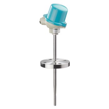
- Sensor ranges -40 ... +1,200 °C (-40 ... +2,192 °F)
- Easily exchanged, no thermowell necessary
- For screw-fitting, welding or using a tightening strap
- Cable from PVC, silicone, PTFE or glass fibre
- Explosion-protected versions
![]()
|
Datasheet
|
|
User Manual
|
|
User Manual
|
|
User Manual
|
- Sensor ranges from -40 ... +1,200 °C (-40 ... 2,192 °F)
- For insertion, screw-in with optional process connection
- Cable from PVC, silicone, PTFE or glass fibre
- High mechanical strength
- Explosion-protected versions
![]()
|
Datasheet
|
|
User Manual
|
|
User Manual
|
|
User Manual
|
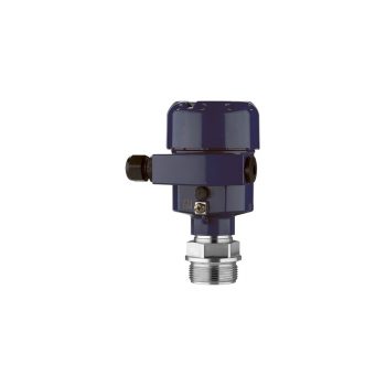
- Case aluminium, epoxy resin coated
- Ingress protection IP 65, NEMA 4
- Ambient temperature -40 ... +85 °C
- 1 switch point, SPDT or DPDT with a high contact rating of up to 15 A/AC 220 V
- Capillary up to 10 m
![]()
![]()
|
Datasheet
|
|
User Manual
|
- Case aluminium, epoxy resin coated
- Ingress protection IP 65, NEMA 4
- Ambient temperature -40 ... +85 °C
- 1 switch point, SPDT or DPDT with a high contact rating of up to 15 A / AC 220 V
- Capillary up to 10 m
![]()
![]()
|
Datasheet
|
|
User Manual
|
- Sensor ranges from -196 ... +600 °C [-320 ... +1,112 °F]
- Measuring insert replaceable
- For many thermowell designs
- Explosion-protected versions are available for many approval types (see data sheet page 2)
![]()
|
Datasheet
|
|
User Manual
|
|
User Manual
|
|
User Manual
|
|
User Manual
|
|
User Manual
|
- 3 times longer service life in comparison to purely ceramic protection tubes due to the monocrystalline structure of the sapphire sensor
- High process safety with processes up to 1,700 °C [3,092 °F] and 65 bar [943 psi]
- Reduction of unplanned downtime
- Increased safety through double sealing system against escape of toxic media
- Cost savings through the elimination of a purge system and the repairability of the sensor
| Datasheet |
| User Manual |
| User Manual |
- Precisely adjustable dual-area spindle pump for filling, pressure generation and fine adjustment of pressure
- Proven technology of the model CPB3800HP dead-weight tester
- Compact dimensions
- Low weight
|
Datasheet
|
|
User Manual
|
- POLARgauge® - special instrument design for extremely low ambient temperatures down to -70 °C [-94 °F]
- Ingress protection IP66 and IP67
- Completely from stainless steel
- Measuring ranges from 0 ... 0.6 to 0 ... 1,000 bar [0 ... 10 to 0 ... 15,000 psi]
- Case also available in safety level “S3” per EN 837-1
|
Datasheet |
|
User Manual
|
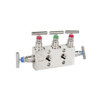
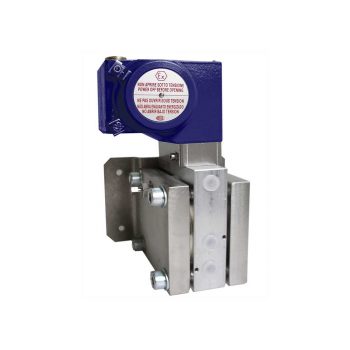
- Low-wear design due to non-rotating spindle tip in the bonnet
- Low torque and smooth operation of valve handle even at high pressure
- Enhanced safety due to blow-out proof bonnet design
- Customer-specific combination of valves and instruments (hook-up) on request
- Standardised centre distances of 37 mm and 54 mm, suitable for WIKA differential pressure gauges and commonly used process transmitters
| Datasheet |
| User Manual |
- Flange with a flush welded diaphragm
- Robust, all welded design
- Universal application
| Datasheet |
| User Manual |
- Double-diaphragm system to ensure the separation of the process and the pressure measuring instrument
- Process connection with thread to provide for direct threaded connection
- All welded version with internal diaphragm
- System from Monel
|
Datasheet |
| User Manual |
- Open flange with internal, all welded diaphragm
- No sealings and clamping elements
- Robust, all welded design
- Compact design
| Datasheet |
| User Manual |
- Process connection with thread to provide for direct threaded connection
- Version with internal diaphragm
- Diaphragm seal parts all welded
- Universal application
| Datasheet |
| User Manual |
- Process connection with thread for direct threaded connection
- Version with internal diaphragm
- Diaphragm seal parts screwed together
- Universal application
| Datasheet |
| User Manual |
- Open flange with internal, all welded diaphragm with diaphragm bed
- No sealings and clamping elements
- Compact design
| Datasheet |
| User Manual |
- Flange with a flush welded diaphragm
- Robust, all welded design
- Universal application
| Datasheet |
| User Manual |
- Process connection with thread to provide for direct threaded connection
- Version with internal diaphragm
- Diaphragm seal parts all welded
- Universal application
|
Datasheet |
| User Manual |
- Process connection with thread for direct threaded connection
- Version with internal diaphragm
- Diaphragm seal parts screwed together
- Universal application
|
Datasheet |
| User Manual |

- No power supply needed for switching of electrical loads
- Setting ranges from -15 ... +20 °C to 180 ... 250 °C
- Repeatability of the set point ≤ 1% span
- 1 set point, SPDT, high switching power up to AC 250 V, 5 A
- Direct mounting or remote mounting with capillary ≤ 10 m
![]()
![]()
|
Datasheet
|
|
User Manual
|
- Process- and procedure-specific production
- Operating limits: - Operating temperature: T = -60 ... +300 °C - Operating pressure: P = Vacuum to 40 bar
- Wide variety of different process connections
- Mounting of level sensors and magnetic switches possible as an option
- Explosion-protected versions
| Datasheet |
| User Manual |
| User Manual |
- High-quality machining guarantees smooth operation with low torque and low wear
- Leak-tested tightness in accordance with BS6755 / ISO 5208 leakage rate A
- Large selection of materials and configurations available
- Customer-specific combination of valves and instruments (hook-up) on request
| Datasheet |
- Mit Gehäusefüllung (Typ 263) bei hohen dynamischen Druckbelastungen und Vibrationen
- Typen 262.30 und 263.30: Sicherheitsausführung mit bruchsicherer Trennwand (Solidfront) nach Anforderungen von EN 837-1 und ASME B40.100
- Eignung für besonders aggressive Messstoffe, da sehr hohe Korrosionsbeständigkeit
- EMICOgauge-Ausführung, zur Vermeidung flüchtiger Emissionen
- Anzeigebereiche von 0 … 0,6 bis 0 … 1.000 bar [0 ... 10 bis 0 ... 15.000 psi]
|
Datenblatt
|
|
Bedienungsanleitung
|
|
Bedienungsanleitung
|
- Temperature ranges from -269 ... +400 °C [-452 ... +752 °F]
- Versions for pressure ranges from vacuum to 500 bar [7,252 psi]
- Special versions: High pressure, interface measurement
- Explosion-protected versions
- Signal processing is made using a separate model OSA-SC switching amplifier
| Datasheet |
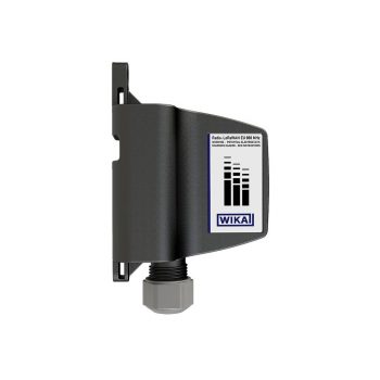
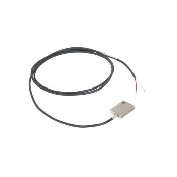
- IIoT-capable with LoRaWAN® transmission
- Battery-operated LoRa® radio transmission based on LPWAN technology
- High transmission range for the measured values (up to 10 km) with long battery life (up to 10 years)
- Exchange of the radio unit possible in ATEX zones
| Datasheet |
| User Manual |
- TÜV certified SIL version for protection systems developed per IEC 61508 (option)
- Operation in safety applications to SIL 2 (single instrument) and SIL 3 (redundant configuration)
- Configurable with almost all soft- and hardware tools
- Universal for the connection of 1 or 2 sensors
- Resistance thermometer, resistance sensor (up to 2 x 3-wire)
- Thermocouple, mV sensor
- Potentiometer
- Signalling in accordance with NAMUR NE43, sensor monitoring in accordance with NE89, EMC in accordance with NE21, self-monitoring and diagnostics of field instruments in accordance with NE107
| Datenblatt |
| Datenblatt |
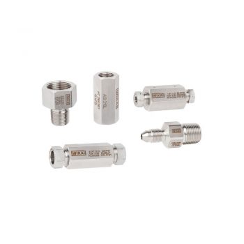
- One-piece design
- Laser marked for identification
- Large selection of materials and configurations available
- Customer-specific combination of adapters, fittings, valves and measuring instruments (instrument hook-up) on request
| Datasheet |
- Common standards and nominal widths available
- When special materials are selected, all wetted parts are made of the selected material
- Version with integrated flushing connections available
| Datasheet |
| User Manual |
- Two fine metering valves for pressure inlet and pressure outlet or vacuum
- Precisely adjustable volume adjuster for fine adjustment of pressure
- Proven technology of the dead-weight tester CPB3500
- Connection for external pressure or vacuum source
- Pressure gauge for indicating the approximate pressure
|
Datasheet
|
|
User Manual
|
- Simplified maintenance and sensor removal without the use of specialised tools
- Maximum surface contact tip design
- High-temperature applications (up to 540 °C [1,000 °F])
|
Datasheet
|
|
User Manual
|
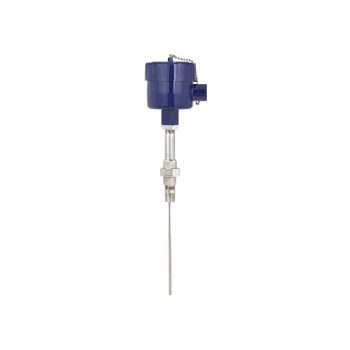
- Sensor ranges from -196 ... +600 °C [-321 ... +1,112 °F]
- The RTD sensor can be mounted into a thermowell or directly into a process with the use of a fixed, spring loaded, or compression fitting
- The assemblies can be supplied with or without transmitters to convert the resistance signal to an analogue or digital output
- The assembly has electrical approvals for explosion proof hazardous locations, ingress protection and general purpose areas.
- Electrical authorities that have registered these approvals include CSA, FM, IECEx and ATEX. The approvals can be with or without an attached thermowell. Our integral flame path is required when supplied without a thermowell
- The RTD sensor is spring loaded ensuring a positive contact to the base of the thermowell (replaceable)
![]()
|
Datasheet
|
|
User Manual
|
|
User Manual
|
|
User Manual
|
- High measurement accuracy
- Freely scalable measuring ranges
- Developed in accordance with the SIL 2 requirements
- Seven different case variants
- Configuration via DTM (Device Type Manager) in accordance with the FDT (Field Device Tool) concept (e.g. PACTware™)
| Datasheet |
| User Manual |
| User Manual |
| User Manual |
- Model OTMT84: PROFIBUS® PA profile 3.02
- Model OTMT85: FOUNDATION™ Fieldbus H1
- Explosion-protected version Ex ia (intrinsically safe/FISCO) and Ex ec available
| Datasheet |
| User Manual |
| User Manual |
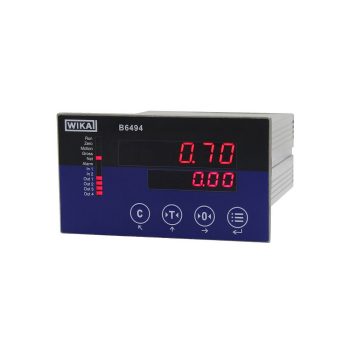
- Dual mV/V display
- 2x digital input and 4x digital output
- Integrated multiple signal outputs available
- Serial interface, RS-232 or RS-485
- Ingress protection IP65
| Datasheet |