


Heating, Ventilation, and Air Conditioning (HVAC)
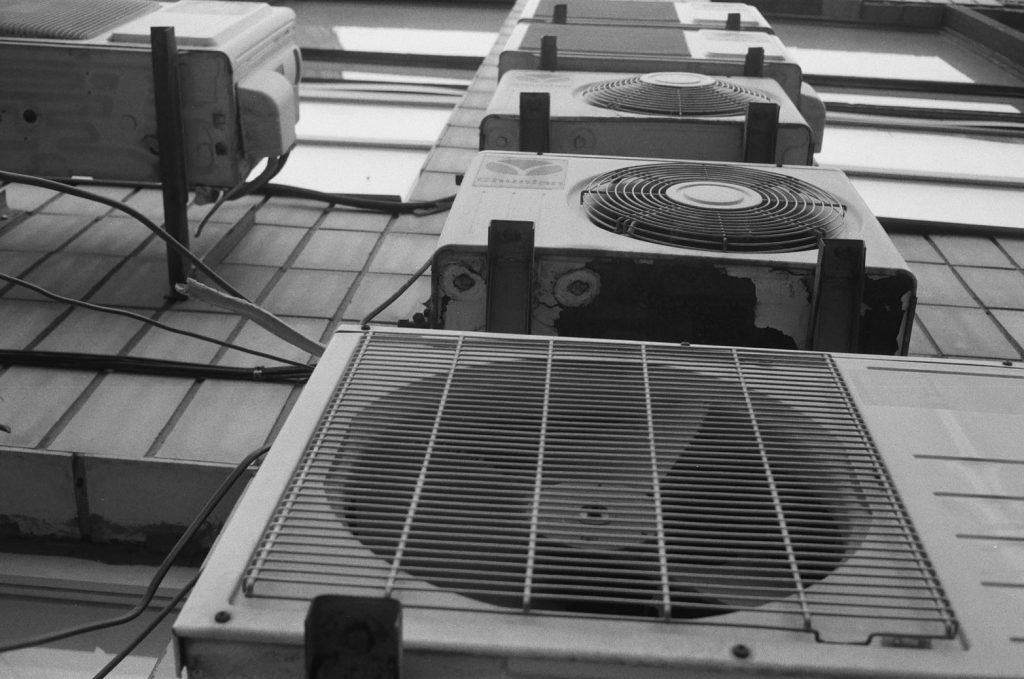
Foto by Illia Horokhovsky on Unsplash
Heating systems Solar thermal systems Combined Heat and Power Plants (CHP) Heat Pumps Gas wall heaters Heat transfer and distribution stations Industrial Boiler Systems Room air handling systems (RLT)
Heating, ventilation, and air conditioning (HVAC) systems are central pillars for comfort and efficiency in modern living and working spaces. The market for these technologies is continuously evolving, driven by increasing awareness of environmental protection, demand for sustainable energy solutions, and the growing digitization of building infrastructure. Innovative, energy-efficient solutions are at the forefront to minimize the ecological footprint while enhancing residential and occupational comfort.
Heating Systems are the backbone of building heating, offering a variety of solutions from traditional gas and oil heaters to modern renewable energy sources.
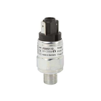
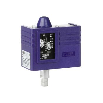
- Setting ranges: 0.2 … 2 bar [3 ... 30 psi] to 30 ... 320 bar [450 ... 4,600 psi] and -0.85 ... -0.15 bar [-25 inHg ... -5 inHg]
- Non-repeatability of the switch point: ≤ 2 % of span
- Switching functions: Normally closed, normally open or change-over contact
- Media: Compressed air, neutral and self-lubricating fluids and neutral gases
 Datasheet Datasheet |
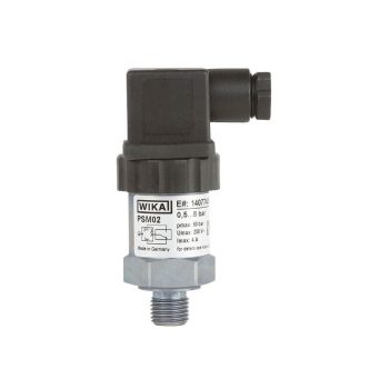
- Adjustable switch hysteresis
- Setting ranges: 0.2 … 2 bar [3 ... 30 psi] to 30 ... 320 bar [450 ... 4,600 psi] and -0.85 ... -0.15 bar [-25 inHg ... -5 inHg]
- Non-repeatability of the switch point: ≤ 2 %
- Switching functions: Normally closed, normally open or change-over contact
- Media: Compressed air, neutral and self-lubricating fluids and neutral gases
 Datasheet Datasheet
|
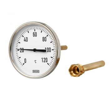
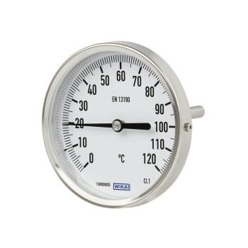
- Accuracy class 2 per EN 13190
- Nominal size 63, 80, 100 and 160
- Scale ranges from -30 ... +200 °C
| Datasheet |
| User Manual |
- Scale ranges from -30 ... +500 °C
- Large choice of nominal sizes from 25 ... 160 mm
- Case and stem from stainless steel
- 5 different connection designs
|
Datasheet
|
|
User Manual
|
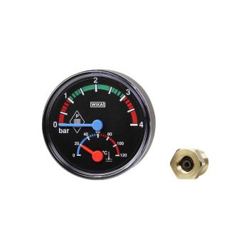
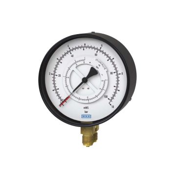
- Combined indication for pressure and temperature
- Scale ranges to 0 … 10 bar [ 0 ... 150 psi] and 0 ... 120 °C [32 ... 248 °F]
- Shut-off valve included in delivery
| Datasheet |
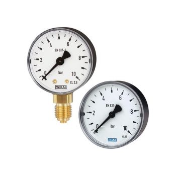
- Reliable and cost-effective
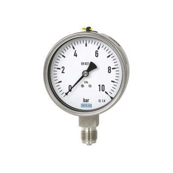
- Design per EN 837-1 or ASME B40.100
- Nominal size 40 [1 ½"], 50 [2"], 63 [2 ½"], 80 [3"], 100 [4"] and 160 [6"]
- Scale ranges to 0 ... 400 bar [0 ... 6,000 psi]
|
Datasheet |
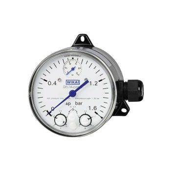
- With one or two adjustable microswitches
- Shatterproof window and robust aluminium or stainless steel measuring chamber for increased requirements
- Optionally with approvals for hazardous areas
- High ingress protection, IP65, for outdoor use and processes with high condensation
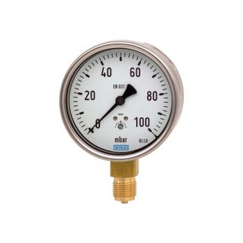
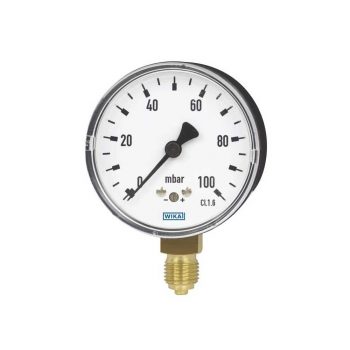
- Low measuring range from 0 ... 250 mbar
| Datasheet |
| User Manual |
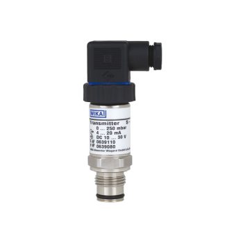
- Transmission of process values to the control room (e.g. 4 ... 20 mA)
- Shatterproof window and robust aluminium or stainless steel measuring chamber for increased requirements
- Optionally with approvals for hazardous areas
- High ingress protection, IP65, for outdoor use and processes with high condensation
- Low measuring range from 0 ... 160 mbar
| Datasheet |
| User Manual |
- Shatterproof window and robust aluminium or stainless steel measuring chamber for increased requirements
- Low scale ranges from 0 ... 160 mbar
- High accuracy down to 1.6 %
- Optionally with approvals for hazardous areas
- Helium leak tested
| Datasheet |
| User Manual |
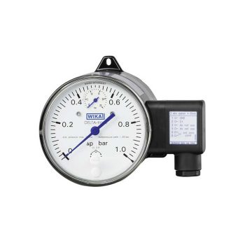
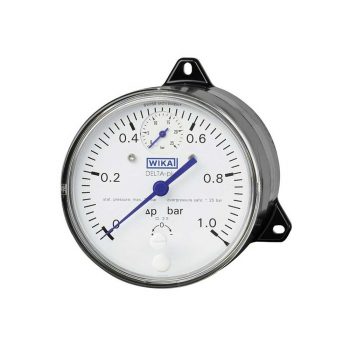
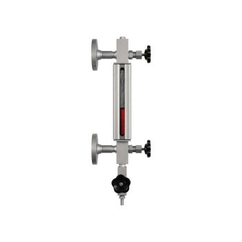
- Scale ranges from 0 ... 0.6 bar to 0 … 1,000 bar
- Two process connections and two independent pointers
- Differential pressure display with moving dial
- Cost-effective and reliable
| Datasheet |
| User Manual |
![]()
|
Datasheet
|
|
User Manual
|
|
User Manual
|
|
User Manual
|
|
User Manual
|
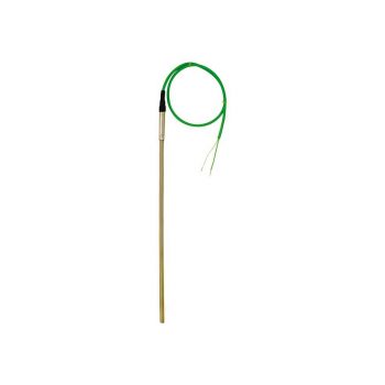
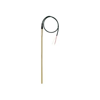
- Sensor ranges from -40 ... +1,200 °C (-40 ... 2,192 °F)
- For insertion, screw-in with optional process connection
- Cable from PVC, silicone, PTFE or glass fibre
- High mechanical strength
- Explosion-protected versions
| Datasheet |
| User Manual |
| User Manual |
| User Manual |
Solar thermal systems harness the energy of the sun to heat water, actively contributing to environmental protection by reducing CO2 emissions. They can be ideally combined with other heating systems to increase efficiency and sustainability.
- Setting ranges: 0.2 … 2 bar [3 ... 30 psi] to 30 ... 320 bar [450 ... 4,600 psi] and -0.85 ... -0.15 bar [-25 inHg ... -5 inHg]
- Non-repeatability of the switch point: ≤ 2 % of span
- Switching functions: Normally closed, normally open or change-over contact
- Media: Compressed air, neutral and self-lubricating fluids and neutral gases
| Datasheet |
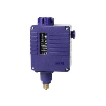
- Adjustable switch hysteresis
- Setting ranges: 0.2 … 2 bar [3 ... 30 psi] to 30 ... 320 bar [450 ... 4,600 psi] and -0.85 ... -0.15 bar [-25 inHg ... -5 inHg]
- Non-repeatability of the switch point: ≤ 2 %
- Switching functions: Normally closed, normally open or change-over contact
- Media: Compressed air, neutral and self-lubricating fluids and neutral gases
|
Datasheet
|
- Accuracy class 2 per EN 13190
- Nominal size 63, 80, 100 and 160
- Scale ranges from -30 ... +200 °C
| Datasheet |
| User Manual |
- Scale ranges from -30 ... +500 °C
- Large choice of nominal sizes from 25 ... 160 mm
- Case and stem from stainless steel
- 5 different connection designs
|
Datasheet
|
|
User Manual
|
- Combined indication for pressure and temperature
- Scale ranges to 0 … 10 bar [ 0 ... 150 psi] and 0 ... 120 °C [32 ... 248 °F]
- Shut-off valve included in delivery
| Datasheet |
- Reliable and cost-effective
- Design per EN 837-1 or ASME B40.100
- Nominal size 40 [1 ½"], 50 [2"], 63 [2 ½"], 80 [3"], 100 [4"] and 160 [6"]
- Scale ranges to 0 ... 400 bar [0 ... 6,000 psi]
|
Datasheet |
![]()
|
Datasheet
|
|
User Manual
|
|
User Manual
|
|
User Manual
|
|
User Manual
|
- Sensor ranges from -40 ... +1,200 °C (-40 ... 2,192 °F)
- For insertion, screw-in with optional process connection
- Cable from PVC, silicone, PTFE or glass fibre
- High mechanical strength
- Explosion-protected versions
| Datasheet |
| User Manual |
| User Manual |
| User Manual |
Combined Heat and Power Plants (CHP) simultaneously generate electricity and heat by utilizing the principle of combined heat and power (CHP). They offer high energy efficiency and can be flexibly deployed in both industrial and municipal as well as private facilities.
- Setting ranges: 0.2 … 2 bar [3 ... 30 psi] to 30 ... 320 bar [450 ... 4,600 psi] and -0.85 ... -0.15 bar [-25 inHg ... -5 inHg]
- Non-repeatability of the switch point: ≤ 2 % of span
- Switching functions: Normally closed, normally open or change-over contact
- Media: Compressed air, neutral and self-lubricating fluids and neutral gases
| Datasheet |
- Adjustable switch hysteresis
- Setting ranges: 0.2 … 2 bar [3 ... 30 psi] to 30 ... 320 bar [450 ... 4,600 psi] and -0.85 ... -0.15 bar [-25 inHg ... -5 inHg]
- Non-repeatability of the switch point: ≤ 2 %
- Switching functions: Normally closed, normally open or change-over contact
- Media: Compressed air, neutral and self-lubricating fluids and neutral gases
|
Datasheet
|
- Accuracy class 2 per EN 13190
- Nominal size 63, 80, 100 and 160
- Scale ranges from -30 ... +200 °C
| Datasheet |
| User Manual |
- Scale ranges from -30 ... +500 °C
- Large choice of nominal sizes from 25 ... 160 mm
- Case and stem from stainless steel
- 5 different connection designs
|
Datasheet
|
|
User Manual
|
- Reliable and cost-effective
- Design per EN 837-1 or ASME B40.100
- Nominal size 40 [1 ½"], 50 [2"], 63 [2 ½"], 80 [3"], 100 [4"] and 160 [6"]
- Scale ranges to 0 ... 400 bar [0 ... 6,000 psi]
|
Datasheet |
![]()
|
Datasheet
|
|
User Manual
|
|
User Manual
|
|
User Manual
|
|
User Manual
|
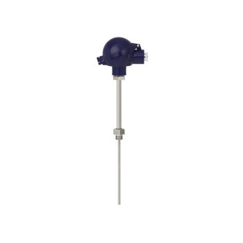
- Sensor ranges from -196 ... +600 °C (-320 ... +1.112 °F)
- For mounting in all standard thermowell designs
- Spring-loaded measuring insert (replaceable)
- Pt100 or Pt1000 sensors
- Explosion-protected versions
![]()
|
Datasheet
|
|
User Manual
|
|
User Manual
|
|
User Manual
|
|
User Manual
|
|
User Manual
|
![]()
|
Datasheet
|
|
User Manual
|
|
Datasheet |
| User Manual |
- Excellent load-cycle stability and shock resistance
- All stainless steel construction
- German Lloyd approva
- Scale ranges up to 0 … 1,600 bar
| Datasheet |
| User Manual |
| User Manual |
| User Manual |
| User Manual |
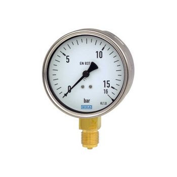
- Very good vibration and shock resistance
- Especially robust design
- Type approval for the shipbuilding industry
- Scale ranges to 0 ... 1,000 bar or 0 ... 15,000 psi
|
Datasheet |
| User Manual |
| User Manual |
| User Manual |
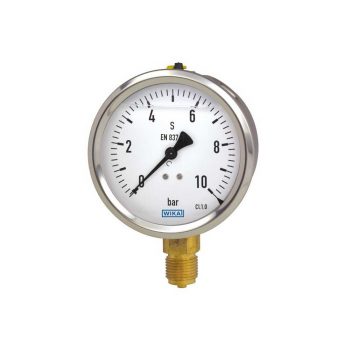
- Long service life, robust
- Cost-effective and reliable
- To combine with WIKA diaphragm seals
- German Lloyd approval
- Scale ranges up to 0 … 1,000 bar
| Datasheet |
| User Manual |
| User Manual |
- With one or two adjustable microswitches
- Shatterproof window and robust aluminium or stainless steel measuring chamber for increased requirements
- Optionally with approvals for hazardous areas
- High ingress protection, IP65, for outdoor use and processes with high condensation
- Low measuring range from 0 ... 250 mbar
| Datasheet |
| User Manual |
- Transmission of process values to the control room (e.g. 4 ... 20 mA)
- Shatterproof window and robust aluminium or stainless steel measuring chamber for increased requirements
- Optionally with approvals for hazardous areas
- High ingress protection, IP65, for outdoor use and processes with high condensation
- Low measuring range from 0 ... 160 mbar
| Datasheet |
| User Manual |
- Shatterproof window and robust aluminium or stainless steel measuring chamber for increased requirements
- Low scale ranges from 0 ... 160 mbar
- High accuracy down to 1.6 %
- Optionally with approvals for hazardous areas
- Helium leak tested
| Datasheet |
| User Manual |
- Scale ranges from 0 ... 0.6 bar to 0 … 1,000 bar
- Two process connections and two independent pointers
- Differential pressure display with moving dial
- Cost-effective and reliable
| Datasheet |
| User Manual |
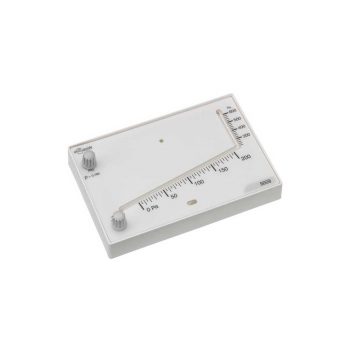
- Zero point correction in front
- Case from stainless steel
- Robust design and ingress protection IP54
- Low scale ranges from 0 ... 6 mbar to 0 ... 600 mbar or 0 ... 2.4 inH2O to 0 ... 240 inH2O
| Datasheet |
| User Manual |
- Zero point setting in front
- Special connection location on request
- Low scale ranges from 0 ... 25 mbar
|
Datasheet |
| User Manual |
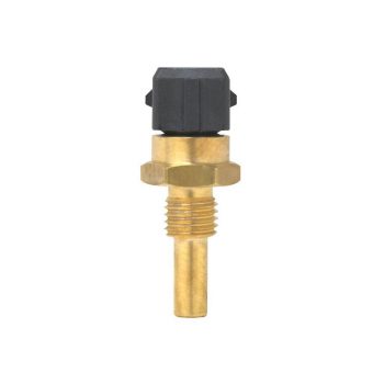
- Sensor ranges from -40 ... +1,200 °C (-40 ... 2,192 °F)
- For insertion, screw-in with optional process connection
- Cable from PVC, silicone, PTFE or glass fibre
- High mechanical strength
- Explosion-protected versions
![]()
|
Datasheet
|
|
User Manual
|
|
User Manual
|
|
User Manual
|
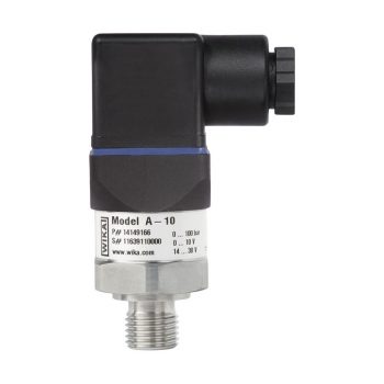
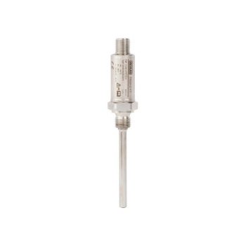
- Measuring ranges from 0 … 0.05 to 0 … 1,000 bar
- Non-linearity 0.25 % or 0.5 %
- Output 4 ... 20 mA, DC 0 ... 10 V, DC 0 ... 5 V and others
- Electrical connection: Angular connector form A and C, circular connector M12 x 1, cable outlet 2 m
- Process connection G ¼ A DIN 3852-E, ¼ NPT and others
|
Datasheet |
| User Manual |
- Maximum reliability thanks to high-quality reed contacts
- Very high variety and customer-specific solutions possible
- Simple and fast installation
| Datasheet |
| User Manual |
- Highest reliability in aggressive media
- Optimum process safety thanks to SMD production
- Simple and fast installation
| Datasheet |
| User Manual |
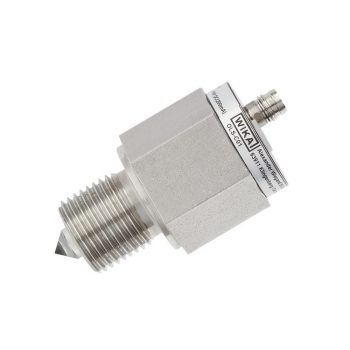
- Compact design, no moving components
- Mounting position as required
- Accuracy ±2 mm
- Visual indication of the switching status
- Choice of electrical connections: PUR, PVC cable or circular connector M8 x 1
| Datasheet |
| User Manual |
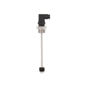
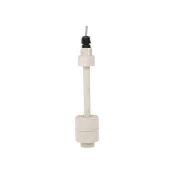
- Freely selectable switch position through fixing the float switch at the required level
- Large range of application due to the simple, proven functional principle
- For harsh operating conditions, long service life
- Operating limits: - Operating temperature: T = -30 ... +150 °C - Operating pressure: P = Vacuum up to 40 bar - Limit density: ρ ≥600 kg/m3
| Datasheet |
| User Manual |
Heat pumps are a key technology for the energy transition in the heating sector. They extract heat from the environment – air, water, or the ground – and convert it into heating energy. Heat pumps are particularly efficient and environmentally friendly, especially when combined with renewable energies.
![]()
|
Datasheet
|
|
User Manual
|
|
User Manual
|
|
User Manual
|
|
User Manual
|
![]()
|
Datasheet
|
|
User Manual
|
|
Datasheet |
| User Manual |
Gas wall heaters offer a space-saving and efficient solution for heat generation in single and multi-family homes. Their compact design and high efficiency make them a popular choice for modern heating systems.
- Combined indication for pressure and temperature
- Scale ranges to 0 … 10 bar [ 0 ... 150 psi] and 0 ... 120 °C [32 ... 248 °F]
- Shut-off valve included in delivery
| Datasheet |
- Setting ranges: 0.2 … 2 bar [3 ... 30 psi] to 30 ... 320 bar [450 ... 4,600 psi] and -0.85 ... -0.15 bar [-25 inHg ... -5 inHg]
- Non-repeatability of the switch point: ≤ 2 % of span
- Switching functions: Normally closed, normally open or change-over contact
- Media: Compressed air, neutral and self-lubricating fluids and neutral gases
| Datasheet |
- Adjustable switch hysteresis
- Setting ranges: 0.2 … 2 bar [3 ... 30 psi] to 30 ... 320 bar [450 ... 4,600 psi] and -0.85 ... -0.15 bar [-25 inHg ... -5 inHg]
- Non-repeatability of the switch point: ≤ 2 %
- Switching functions: Normally closed, normally open or change-over contact
- Media: Compressed air, neutral and self-lubricating fluids and neutral gases
|
Datasheet
|
Heat Transfer and Distribution Stations are central to the distribution of heat in district heating networks. They enable efficient and demand-responsive control of heat supply and contribute to optimizing energy consumption.
- Setting ranges: 0.2 … 2 bar [3 ... 30 psi] to 30 ... 320 bar [450 ... 4,600 psi] and -0.85 ... -0.15 bar [-25 inHg ... -5 inHg]
- Non-repeatability of the switch point: ≤ 2 % of span
- Switching functions: Normally closed, normally open or change-over contact
- Media: Compressed air, neutral and self-lubricating fluids and neutral gases
| Datasheet |
- Adjustable switch hysteresis
- Setting ranges: 0.2 … 2 bar [3 ... 30 psi] to 30 ... 320 bar [450 ... 4,600 psi] and -0.85 ... -0.15 bar [-25 inHg ... -5 inHg]
- Non-repeatability of the switch point: ≤ 2 %
- Switching functions: Normally closed, normally open or change-over contact
- Media: Compressed air, neutral and self-lubricating fluids and neutral gases
|
Datasheet
|
- Accuracy class 2 per EN 13190
- Nominal size 63, 80, 100 and 160
- Scale ranges from -30 ... +200 °C
| Datasheet |
| User Manual |
- Scale ranges from -30 ... +500 °C
- Large choice of nominal sizes from 25 ... 160 mm
- Case and stem from stainless steel
- 5 different connection designs
|
Datasheet
|
|
User Manual
|
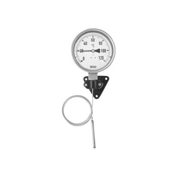
- Case and stem made of stainless steel
- Design per DIN EN 13190
- Different designs of connection and mounting
- With capillary
- With various fixed connections
|
Datasheet
|
|
User Manual
|
![]()
|
Datasheet
|
|
User Manual
|
![]()
|
Datasheet
|
|
User Manual
|
|
User Manual
|
|
User Manual
|
|
User Manual
|
|
Datasheet |
| User Manual |
- Reliable and cost-effective
- Design per EN 837-1 or ASME B40.100
- Nominal size 40 [1 ½"], 50 [2"], 63 [2 ½"], 80 [3"], 100 [4"] and 160 [6"]
- Scale ranges to 0 ... 400 bar [0 ... 6,000 psi]
|
Datasheet |
- Excellent load-cycle stability and shock resistance
- All stainless steel construction
- German Lloyd approva
- Scale ranges up to 0 … 1,600 bar
| Datasheet |
| User Manual |
| User Manual |
| User Manual |
| User Manual |
- Very good vibration and shock resistance
- Especially robust design
- Type approval for the shipbuilding industry
- Scale ranges to 0 ... 1,000 bar or 0 ... 15,000 psi
|
Datasheet |
| User Manual |
| User Manual |
| User Manual |
- Long service life, robust
- Cost-effective and reliable
- To combine with WIKA diaphragm seals
- German Lloyd approval
- Scale ranges up to 0 … 1,000 bar
| Datasheet |
| User Manual |
| User Manual |
- With one or two adjustable microswitches
- Shatterproof window and robust aluminium or stainless steel measuring chamber for increased requirements
- Optionally with approvals for hazardous areas
- High ingress protection, IP65, for outdoor use and processes with high condensation
- Low measuring range from 0 ... 250 mbar
| Datasheet |
| User Manual |
- Transmission of process values to the control room (e.g. 4 ... 20 mA)
- Shatterproof window and robust aluminium or stainless steel measuring chamber for increased requirements
- Optionally with approvals for hazardous areas
- High ingress protection, IP65, for outdoor use and processes with high condensation
- Low measuring range from 0 ... 160 mbar
| Datasheet |
| User Manual |
- Shatterproof window and robust aluminium or stainless steel measuring chamber for increased requirements
- Low scale ranges from 0 ... 160 mbar
- High accuracy down to 1.6 %
- Optionally with approvals for hazardous areas
- Helium leak tested
| Datasheet |
| User Manual |
- Scale ranges from 0 ... 0.6 bar to 0 … 1,000 bar
- Two process connections and two independent pointers
- Differential pressure display with moving dial
- Cost-effective and reliable
| Datasheet |
| User Manual |
- Measuring ranges from 0 … 0.05 to 0 … 1,000 bar
- Non-linearity 0.25 % or 0.5 %
- Output 4 ... 20 mA, DC 0 ... 10 V, DC 0 ... 5 V and others
- Electrical connection: Angular connector form A and C, circular connector M12 x 1, cable outlet 2 m
- Process connection G ¼ A DIN 3852-E, ¼ NPT and others
|
Datasheet |
| User Manual |
Industrial boiler systems are capable of providing large quantities of steam or hot water for industrial processes. Advances in condensing technology and the use of sustainable fuels continuously enhance their efficiency and environmental friendliness.
- Reliable and cost-effective
- Design per EN 837-1 or ASME B40.100
- Nominal size 40 [1 ½"], 50 [2"], 63 [2 ½"], 80 [3"], 100 [4"] and 160 [6"]
- Scale ranges to 0 ... 400 bar [0 ... 6,000 psi]
|
Datasheet |
- Excellent load-cycle stability and shock resistance
- All stainless steel construction
- German Lloyd approva
- Scale ranges up to 0 … 1,600 bar
| Datasheet |
| User Manual |
| User Manual |
| User Manual |
| User Manual |
- Very good vibration and shock resistance
- Especially robust design
- Type approval for the shipbuilding industry
- Scale ranges to 0 ... 1,000 bar or 0 ... 15,000 psi
|
Datasheet |
| User Manual |
| User Manual |
| User Manual |
- Long service life, robust
- Cost-effective and reliable
- To combine with WIKA diaphragm seals
- German Lloyd approval
- Scale ranges up to 0 … 1,000 bar
| Datasheet |
| User Manual |
| User Manual |
- Measuring ranges from 0 … 0.05 to 0 … 1,000 bar
- Non-linearity 0.25 % or 0.5 %
- Output 4 ... 20 mA, DC 0 ... 10 V, DC 0 ... 5 V and others
- Electrical connection: Angular connector form A and C, circular connector M12 x 1, cable outlet 2 m
- Process connection G ¼ A DIN 3852-E, ¼ NPT and others
|
Datasheet |
| User Manual |
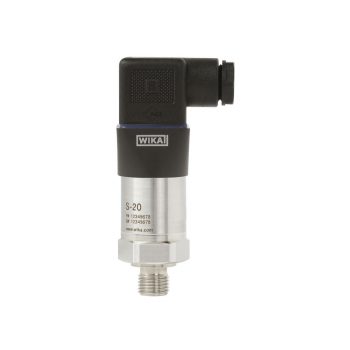
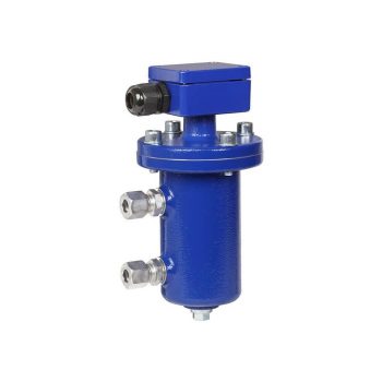
- High-quality product
- Many configurations possible
- Flush process connection
- Large stocks for short delivery times
- Vacuum-tight
| Datasheet |
| User Manual |
- Adjustable on site
- Protection cap for switch point adjustment
- Setting ranges: -0.4 ... +7 to 6 ... 30 bar -6 ...100 to 85 ... 425 psi -0.04 ... +0.7 to 0.6 ... 3 MPa
- Electrical rating up to AC 230 V, 50/60 Hz, 10 A
| Datasheet |
| User Manual |
- Process- and procedure-specific production
- Operating limits: - Operating temperature: -196 ... +374 °C 1) - Operating pressure: Vacuum to 250 bar 1)
- Wide variety of different process connections and materials
- Illumination optional
- Heating and/or insulation optional
| Datasheet |
| User Manual |
| User Manual |
Room air handling units (RLT) ensure a healthy and comfortable indoor climate by regulating temperature, humidity, and air quality. Innovative filter technologies and heat recovery systems optimize energy usage and contribute to improving indoor air quality.
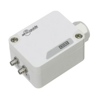
- Output signal 0 ... 10 V or 4 ... 20 mA
- Maintenance-free
- Simple operation
- High accuracy
| Datasheet |
| User Manual |
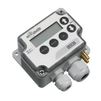
- Electrical output signal 0 ... 10 V or 4 ... 20 mA, can be selected directly at the instrument via jumpers
- Modbus® output signal (option)
- LC display (option)
- Maintenance-free
- Maximum operating pressure 20 kPa
| Datasheet |
| User Manual |
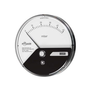
- Very small insertion depth
- Simple and fast mounting via threaded bezel
- Separated construction of measuring chamber and display area
- Integrated sealing element for direct mounting in a ventilation duct
- Individual design of dial and scale possible
| Datasheet |
| User Manual |
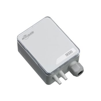
- Electrical output signal 0 ... 10 V (3-wire)
- Simple and quick mounting
- Maintenance-free
- Maximum operating pressure 20 kPa
| Datasheet |
| User Manual |
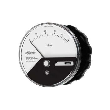
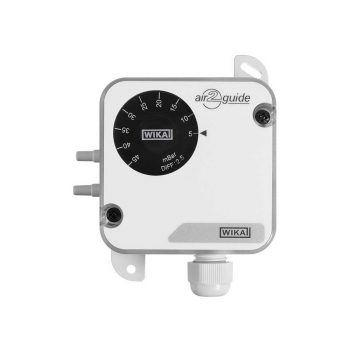
- Fast, tool-free mounting via threaded bezel
- Separated construction of pressure measurement chamber and display area
- Integrated sealing element for direct installation in a ventilation duct or instrument panel
- Available as a built-in or add-on version
- Individual design of dial and scale possible
| Datasheet |
| User Manual |
For ventilation and air-conditioning
Datenblatt
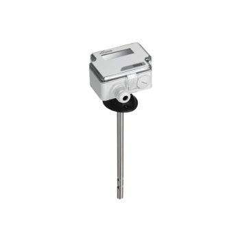
- Electrical output signal DC 0 … 10 V or 4 … 20 mA, can be selected directly at the instrument via jumpers
- Output signal for velocity and air temperature in one instrument
- With switching output
- Mounting flange for mounting on circular ventilation pipes or rectangular ventilation ducts
- Maintenance-free
|
Datasheet
|
|
User Manual
|
- Simple mounting
- Compact and heavy-duty version
- High reproducibility
- Integrated switching output
- With automatic resetting
| Datasheet |
| User Manual |
The development and implementation of advanced control and monitoring systems for all of these technologies is crucial to optimize their operation and further enhance their efficiency. The use of IoT (Internet of Things) technologies for smart control and monitoring allows minimizing energy consumption and maximizing user comfort. Reliable and innovative partners distinguished by experience, technical know-how, and a clear vision for the future are essential to tackle the challenges on the path towards more sustainable and efficient heating, ventilation, and air conditioning techniques.