


Industrial gases
In industries such as metal processing, water treatment, medicine, healthcare, or firefighting, the supply technology for industrial and medical gases plays a crucial role. It enables the effective and sustainable handling, distribution, and use of compressed and liquid air types as well as chemical gases. The use of such gases is subject to strict standards and guidelines, with special emphasis on occupational safety, energy and labor cost savings, and supply chain efficiency. To cope with these complex requirements, we offer a wide-ranging portfolio of measuring instruments that supports a variety of applications and meets the most diverse requirements.
Applications
Measuring instruments in cryogenic tanks, ISO containers, and tanker trailers play a crucial role in monitoring the levels of cryogenic liquids. These instruments, including pressure gauges, provide an indication of absolute pressure or differential pressure and, in tanker trailers, additionally capture the pressure before and after the cryo pump.
Based on the specific requirements of original equipment manufacturers (OEMs) and gas supply companies, these containers and trailers are equipped with integrated or externally mounted transmitters. Our clients in this sector include manufacturers of cryogenic storage containers, maintenance and repair services for such containers, industrial gas traders, leasing companies for ISO containers, and suppliers of related cryogenic monitoring systems.
- Very good vibration and shock resistance
- Especially robust design
- Type approval for the shipbuilding industry
- Scale ranges to 0 ... 1,000 bar or 0 ... 15,000 psi
 Datasheet Datasheet |
| User Manual |
| User Manual |
| User Manual |
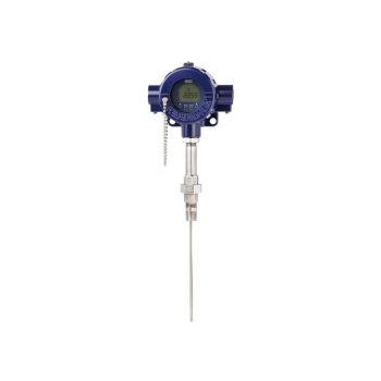
- For many variants of temperature transmitters including field transmitter
- For mounting in all standard thermowell designs
- Spring-loaded measuring insert (replaceable)
- Explosion-protected versions (option)
![]()
|
Datasheet
|
|
User Manual
|
|
User Manual
|
|
User Manual
|
|
User Manual
|
- Measuring ranges strains from 0 ... 200 με up to max. 0 ... 1,000 με
- Good long-term stability, high shock and vibration resistance, good reproducibility
- As retrofitting, easy to install
- For use in extreme outdoor applications (IP67)
- Relative linearity error < 2 % Fnom
 Datasheet Datasheet |
| User Manual |
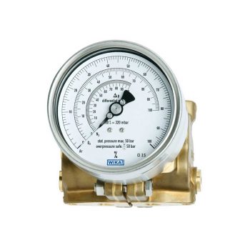
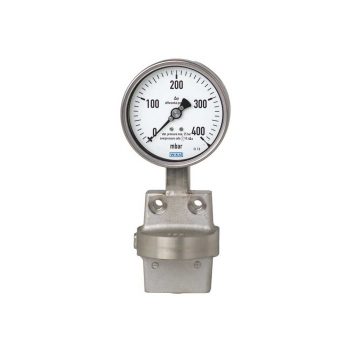
- Differential pressure measuring ranges from 0 … 40 mbar to 0 ... 4,000 mbar
- High working pressure (static pressure) of 50 bar
- Overpressure safety either side up to 50 bar
- Scalable measuring ranges (maximum turndown of 1 : 3.5)
- Compact valve manifold with working pressure indication (optional)
| Datasheet |
| User Manual |
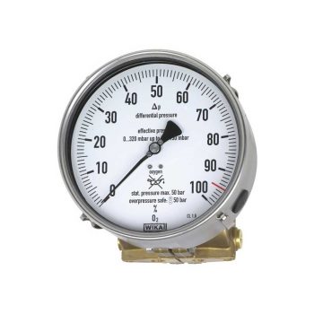
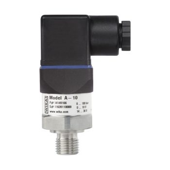
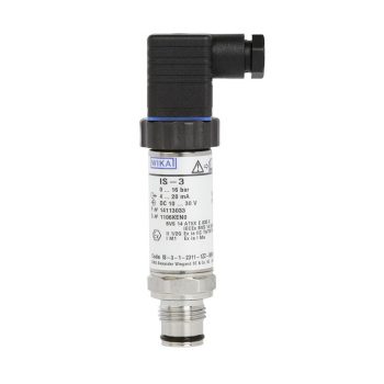
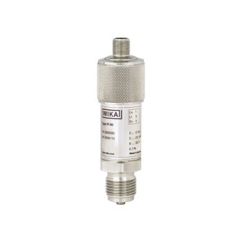
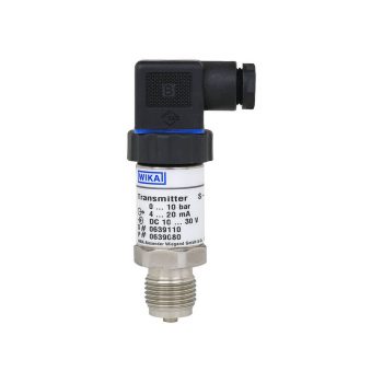
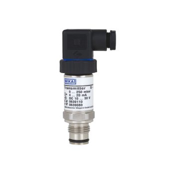
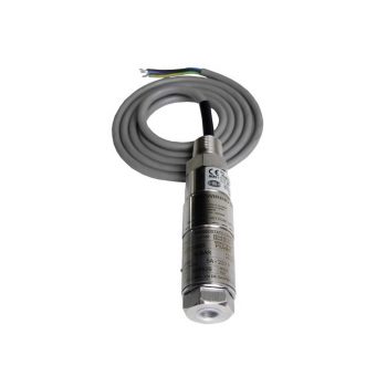
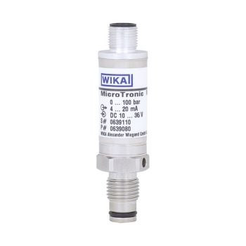
- Measuring ranges from 0 … 0.05 to 0 … 1,000 bar
- Non-linearity 0.25 % or 0.5 %
- Output 4 ... 20 mA, DC 0 ... 10 V, DC 0 ... 5 V and others
- Electrical connection: Angular connector form A and C, circular connector M12 x 1, cable outlet 2 m
- Process connection G ¼ A DIN 3852-E, ¼ NPT and others
|
Datasheet |
| User Manual |
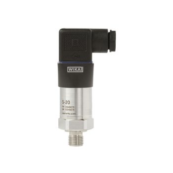
- Measuring ranges from 0 ... 0.1 to 0 ... 6,000 bar [0 ... 3 to 0 ... 15,000 psi]
- Approved for use in hazardous areas, e.g. ATEX, IECEx, FM and CSA
| Datasheet |
| User Manual |
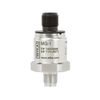
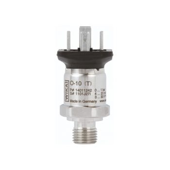
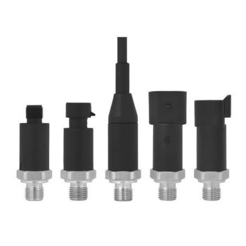
- Measuring ranges from 0 … 6 to 0 … 16 bar [0 ... 100 to 0 ... 200 psi] and from 0 … 200 to 0 … 400 bar [0 ... 3,000 to 0 ... 5,000 psi]
- Output signals 4 … 20 mA, DC 0 … 10 V, DC 0 … 5 V, DC 1 ... 5 V, DC 0.5 … 4.5 V ratiometric
- Oxygen clean in accordance with international standards
- Available in four levels of cleanliness
- Three packaging variants
| Datasheet |
| User Manual |
- Temperature ranges from -269 … +400 °C
- Versions for pressure ranges from vacuum to 500 bar
- Special versions: High pressure, interface measurement
- Signal processing is made using a separate model OSA-S switching amplifier
| Datasheet |
| Datasheet |
| User Manual |
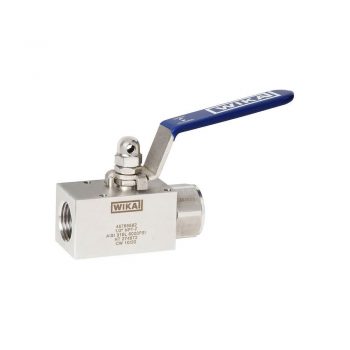
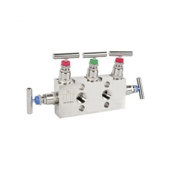
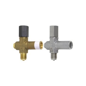
- High-quality machining guarantees smooth operation with low torque and low wear
- Leak-tested tightness in accordance with BS6755 / ISO 5208 leakage rate A
- Large selection of materials and configurations available
- Customer-specific combination of valves and instruments (hook-up) on request
| Datasheet |
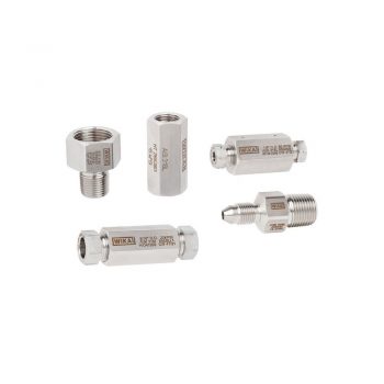
- One-piece design
- Laser marked for identification
- Large selection of materials and configurations available
- Customer-specific combination of adapters, fittings, valves and measuring instruments (instrument hook-up) on request
| Datasheet |
- High measurement accuracy
- Freely scalable measuring ranges
- Developed in accordance with the SIL 2 requirements
- Seven different case variants
- Configuration via DTM (Device Type Manager) in accordance with the FDT (Field Device Tool) concept (e.g. PACTware™)
| Datasheet |
| User Manual |
| User Manual |
| User Manual |
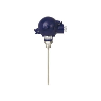
- Sensor ranges from -196 ... +600 °C [-320 ... +1,112 °F]
- For insertion, screw-in with optional process connection
- Connection head form B or JS
- Explosion-protected versions are available for many approval types (see data sheet page 2)
![]()
|
Datasheet
|
|
User Manual
|
|
User Manual
|
|
User Manual
|
|
User Manual
|
|
User Manual
|
Pressure gauges with Bourdon tubes are a central element in welding pressure reducers, both in classic versions with the traditional “Mickey Mouse” layout and in modern regulator modules integrated into plastic housings.
One instrument measures the pressure in the gas tanks, while the other monitors the set working pressure in the supply line. These measuring devices are used not only in standard welding technology with brass pressure reducers but also on nickel-plated pressure reducers in laboratories and in the industry for specialty gases, as well as in the beverage distribution sector.
The users in this field include OEM valve manufacturers, gas suppliers, distributors, and producers of welding equipment, as well as beverage and other industrial applications.
- High-quality machining guarantees smooth operation with low torque and low wear
- Leak-tested tightness in accordance with BS6755 / ISO 5208 leakage rate A
- Large selection of materials and configurations available
- Customer-specific combination of valves and instruments (hook-up) on request
| Datasheet |
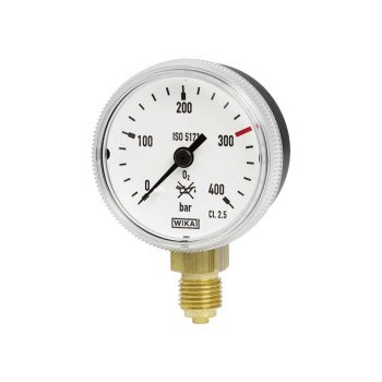
- Version per ISO 5171 or for acetylene per ISO 7291
- Safety features Model 111.11: With blow-out device in case back Model 111.31: With solid baffle wall (Solidfront)
- Nominal size (NS) of the case Model 111.11: NS 40, 50 and 63 Model 111.31: NS 50
- Scale ranges to 0 ... 400 bar or 0 ... 6,000 psi
| Datasheet |
| User Manual |
- Accuracy 0.1 %, without additional temperature error in a range of 10 ... 60 °C
- Optional accuracy of 0.05 % (full scale) available
- Fast measuring rates up to 1 kHz
- Analogue, USB and CANopen® output signals available
- On-site calibration possible using product software
| Datasheet |
| User Manual |
We work with several renowned manufacturers of valves and pressure reducers. Over time, the design of these regulators has continuously evolved to ensure enhanced protection and easier operation of measuring instruments.
This development has led to the integration of measuring instruments directly into the valves, known as VIPR (Valve with Integrated Pressure Regulator). Initially, mechanical versions were used, which were later replaced by mechatronic or electronic instruments.
The main function of the measuring instruments in such pressure reducers is to measure the pressure both in the gas container and in the supply line. Modern electronic versions offer additional features, such as displaying the remaining operating time, gas throughput, and fill level, they trigger alarms at low gas content, and enable wireless communication.
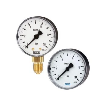
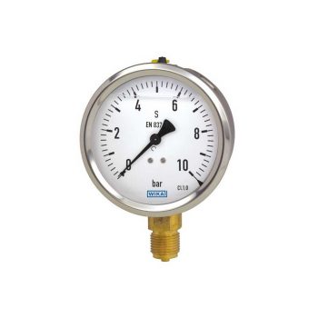
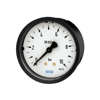
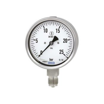
- Reliable and cost-effective
- Design per EN 837-1 or ASME B40.100
- Nominal size 40 [1 ½"], 50 [2"], 63 [2 ½"], 80 [3"], 100 [4"] and 160 [6"]
- Scale ranges to 0 ... 400 bar [0 ... 6,000 psi]
|
Datasheet |
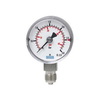
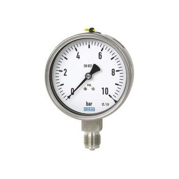
- Case and wetted parts from stainless steel
- Version per EN 837-1 or ASME B40.100
- Cost-effective and reliable
- Scale ranges from 0 ... 1 to 0 … 1,000 bar [0 ... 15 to 0 ... 15,000 psi]
|
Datasheet |
| User Manual |
| User Manual |
- Measuring ranges from 0 ... 6 bar to 0 ... 600 bar
- Non-linearity 0.5 %
- Standard industrial signals
- Electrical connection: Angular connector form A and C, circular connector M12 x 1, Metri-Pack series 150, cable outlet 2 m unshielded or shielded
- Many internationally customary process connections
| Datasheet |
| User Manual |
Gas cylinder cabinets primarily serve to protect against fires and to safely store gas cylinders that contain inert, non-reactive, and harmless gases. Various models of these cabinets are available on the market, which come in different sizes for storing from one to several gas cylinders and can be tailored to the needs of individual companies. These cabinets can be purchased new, bought used, or reused after refurbishment.
Depending on the requirements posed by the stored gas, gas cylinder cabinets can be equipped with various safety features. These include gas detectors, sprinkler systems, overflow alarms, as well as an automatic control system that offers features like automatic ventilation and pressure relief. Furthermore, the specifications of the connections and valves are crucial for selecting compatible measuring and control instruments to ensure effective and safe gas distribution.
These cabinets not only contribute to occupational safety by protecting against potential hazards such as leaks or pressure increases but also support compliance with legal safety regulations. The integration of advanced monitoring technologies allows for continuous monitoring of the gas cylinders, contributing to preventive maintenance and the avoidance of operational disruptions.
- Measuring ranges from 0 … 6 to 0 … 16 bar [0 ... 100 to 0 ... 200 psi] and from 0 … 200 to 0 … 400 bar [0 ... 3,000 to 0 ... 5,000 psi]
- Output signals 4 … 20 mA, DC 0 … 10 V, DC 0 … 5 V, DC 1 ... 5 V, DC 0.5 … 4.5 V ratiometric
- Oxygen clean in accordance with international standards
- Available in four levels of cleanliness
- Three packaging variants
| Datasheet |
| User Manual |
- High-quality machining guarantees smooth operation with low torque and low wear
- Leak-tested tightness in accordance with BS6755 / ISO 5208 leakage rate A
- Large selection of materials and configurations available
- Customer-specific combination of valves and instruments (hook-up) on request
| Datasheet |
- High overload protection up to 400 %
- 0.1 % FS Accuracy
- Meets the highest EMC requirements
- Measuring ranges 0 ... 27.22 kg to 0 ... 136.08 kg [0 ... 60 lbs to 0 ... 300 lbs]
- High ingress protection, IP65, for outdoor use and processes with high condensation
| Datasheet |
| User Manual |
- One-piece design
- Laser marked for identification
- Large selection of materials and configurations available
- Customer-specific combination of adapters, fittings, valves and measuring instruments (instrument hook-up) on request
| Datasheet |
Medical gases play a crucial role in numerous areas of healthcare, including emergency rooms, operating theaters, intensive care units, patient rooms, and in emergency vehicles. These gases, which include medical air, carbon dioxide (CO2), helium (He), nitrous oxide (N2O), nitrogen (N2), nitric oxide (NO), oxygen (O2), and xenon, are indispensable for a variety of treatments and therapies.
To ensure a continuous and safe supply of these vital gases, measuring instruments are used at various points in the supply system, including storage tanks, gas cylinders, valve connections, pressure regulators, and at the points where the gases are administered to patients. Vacuum gauges are used to control the vacuum in the supply systems. The reliability of these measuring instruments is crucial to ensure patient safety and to enable precise dosing of medical gases. The consumers of these technologies include manufacturers of medical devices, companies that supply medical gases, as well as producers of pressure regulation technology for medical applications. The implementation of these measuring devices significantly contributes to improving the quality of patient care and increasing the efficiency of medical treatments.
- Measuring ranges from 0 … 6 to 0 … 16 bar [0 ... 100 to 0 ... 200 psi] and from 0 … 200 to 0 … 400 bar [0 ... 3,000 to 0 ... 5,000 psi]
- Output signals 4 … 20 mA, DC 0 … 10 V, DC 0 … 5 V, DC 1 ... 5 V, DC 0.5 … 4.5 V ratiometric
- Oxygen clean in accordance with international standards
- Available in four levels of cleanliness
- Three packaging variants
| Datasheet |
| User Manual |
- High-quality machining guarantees smooth operation with low torque and low wear
- Leak-tested tightness in accordance with BS6755 / ISO 5208 leakage rate A
- Large selection of materials and configurations available
- Customer-specific combination of valves and instruments (hook-up) on request
| Datasheet |
- Reliable and cost-effective
- Design per EN 837-1 or ASME B40.100
- Nominal size 40 [1 ½"], 50 [2"], 63 [2 ½"], 80 [3"], 100 [4"] and 160 [6"]
- Scale ranges to 0 ... 400 bar [0 ... 6,000 psi]
|
Datasheet |
- Specifically for panel mounting
- Reliable and cost-effective
- Version per EN 837-1 or ASME B40.100
- Scale ranges to 0 ... 400 bar or 0 ... 6,000 psi
|
Datasheet |
| User Manual |
- Very good vibration and shock resistance
- Especially robust design
- Type approval for the shipbuilding industry
- Scale ranges to 0 ... 1,000 bar or 0 ... 15,000 psi
|
Datasheet |
| User Manual |
| User Manual |
| User Manual |
- Differential pressure measuring ranges from 0 … 40 mbar to 0 ... 4,000 mbar
- High working pressure (static pressure) of 50 bar
- Overpressure safety either side up to 50 bar
- Scalable measuring ranges (maximum turndown of 1 : 3.5)
- Compact valve manifold with working pressure indication (optional)
| Datasheet |
| User Manual |
- Measuring ranges from 0 … 0.05 to 0 … 1,000 bar
- Non-linearity 0.25 % or 0.5 %
- Output 4 ... 20 mA, DC 0 ... 10 V, DC 0 ... 5 V and others
- Electrical connection: Angular connector form A and C, circular connector M12 x 1, cable outlet 2 m
- Process connection G ¼ A DIN 3852-E, ¼ NPT and others
|
Datasheet |
| User Manual |
- Measuring ranges from 0 ... 6 bar to 0 ... 600 bar
- Non-linearity 0.5 %
- Standard industrial signals
- Electrical connection: Angular connector form A and C, circular connector M12 x 1, Metri-Pack series 150, cable outlet 2 m unshielded or shielded
- Many internationally customary process connections
| Datasheet |
| User Manual |
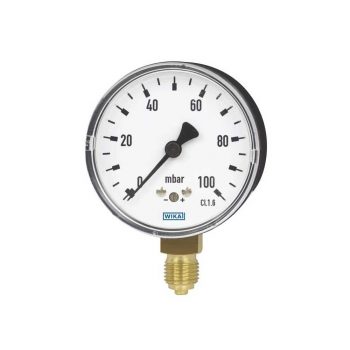
- Zero point setting in front
- Special connection location on request
- Low scale ranges from 0 ... 25 mbar
|
Datasheet |
| User Manual |
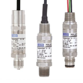
- Measuring ranges from 0 ... 0.1 to 0 ... 1,000 bar
- Non-linearity 0.2 % of span (BFSL)
- Output signals: 4 ... 20 mA, DC 0 ... 10 V, DC 0 ... 5 V and others
- Electrical connections: Angular connector form A, circular connector M12 x 1, various cable outlets and others
- Zero point and span adjustable via internal potentiometer
| Datasheet |
| User Manual |
Hydrogen plays a key role as a source of energy and finds wide application due to its high energy content. In fuel cells, it is used to generate electricity through the chemical reaction with oxygen, making it a clean fuel for vehicles, spacecraft, remote weather stations, and submarines. In addition, hydrogen is significant in the production of fertilizers and paints and finds diverse uses in food processing, chemical laboratories, and welding technology, especially in TIG and plasma welding.
In the chemical industry, hydrogen is an essential reducing agent that places special requirements on the material resistance of the instruments used. Companies from the automotive industry, petrol station construction, development of gas supply systems, laboratory testing technology, and gas analysis employ instruments for hydrogen applications and demand the highest precision and reliability. Moreover, hydrogen contributes to the energy transition by serving as a storage medium for renewable energies and is used in steel production and the energy sector as a replacement for fossil fuels to reduce CO2 emissions.
- High-quality machining guarantees smooth operation with low torque and low wear
- Leak-tested tightness in accordance with BS6755 / ISO 5208 leakage rate A
- Large selection of materials and configurations available
- Customer-specific combination of valves and instruments (hook-up) on request
| Datasheet |
- Differential pressure measuring ranges from 0 … 40 mbar to 0 ... 4,000 mbar
- High working pressure (static pressure) of 50 bar
- Overpressure safety either side up to 50 bar
- Scalable measuring ranges (maximum turndown of 1 : 3.5)
- Compact valve manifold with working pressure indication (optional)
| Datasheet |
| User Manual |
- High-quality product
- Many configurations possible
- Flush process connection
- Large stocks for short delivery times
- Vacuum-tight
| Datasheet |
| User Manual |
- For extreme operating conditions
- Compact and robust design
- Diagnostic function (option)
- Signal clamping (option)
- Customer-specific modifications possible
| Datasheet |
| User Manual |
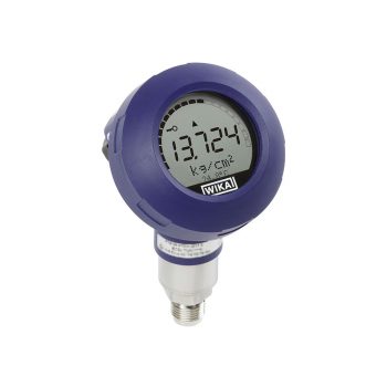
- Multi-functional display
- Simple menu navigation
- Conductive plastic case
- Large LC display, rotatable
- Approvals for hazardous areas
| Datasheet |
| User Manual |
- Differential pressure measuring ranges from 0 ... 16 mbar to 0 ... 40 bar or 0 ...10 inH2O to 0 ... 600 psi
- High operating pressure (static pressure) up to 40 bar [600 psi]
- High overload safety up to 40 bar [600 psi]
- Models 732.31 and 733.31: Case with safety level “S3” per EN 837
- All-welded media chamber
| Datasheet |
| User Manual |
| User Manual |
- Excellent load-cycle stability and shock resistance
- All stainless steel construction
- German Lloyd approva
- Scale ranges up to 0 … 1,600 bar
| Datasheet |
| User Manual |
| User Manual |
| User Manual |
| User Manual |
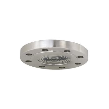
- Flange with flush welded diaphragm
- Common standards and nominal widths available
- Wide variety of different materials and material combinations
| Datasheet |
| User Manual |
- Versions to customer specification
- Various process connections
- Short response times
- Robust, vibration-resistant design
- Various thermocouple types and electrical connection types
| Datasheet |
| Datasheet |
| User Manual |
| User Manual |
| User Manual |
- One-piece design
- Laser marked for identification
- Large selection of materials and configurations available
- Customer-specific combination of adapters, fittings, valves and measuring instruments (instrument hook-up) on request
| Datasheet |
- Sensor ranges from -196 ... +600 °C [-320 ... +1,112 °F]
- For insertion, screw-in with optional process connection
- Connection head form B or JS
- Explosion-protected versions are available for many approval types (see data sheet page 2)
![]()
|
Datasheet
|
|
User Manual
|
|
User Manual
|
|
User Manual
|
|
User Manual
|
|
User Manual
|
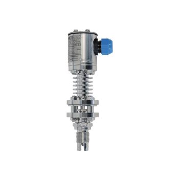
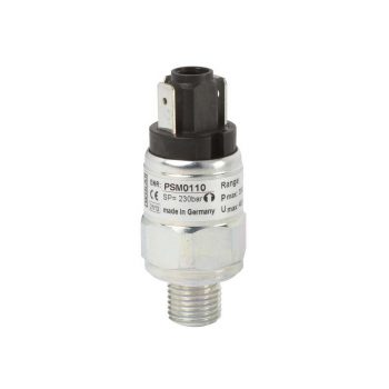
The great advantage of mechanical pressure switches is that no supply voltage is required for the switching process.
- Compact and slim design
- Robust switch enclosure from stainless steel 316, IP66, NEMA 4X
- Wide selection of setting ranges available, 1 … 2.5 bar to 200 … 1,000 bar
- Set point repeatability of ≤ 1 % for reliable switching
- High switching power and large selection of contact variants and electrical connections
| Datasheet |
| User Manual |
- Low-wear design due to non-rotating spindle tip in the bonnet
- Low torque and smooth operation of valve handle even at high pressure
- Enhanced safety due to blow-out proof bonnet design
- Customer-specific combination of valves and instruments (hook-up) on request
- Standardised centre distances of 37 mm and 54 mm, suitable for WIKA differential pressure gauges and commonly used process transmitters
| Datasheet |
| User Manual |
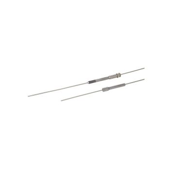
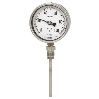
- Scale ranges from -70 ... +600 °C
- For extreme ambient temperatures
- Maintenance-friendly bayonet case
- All stainless steel construction
- Individual stem length from 63 ... 1,000 mm
![]()
|
Datasheet
|
|
User Manual
|
|
User Manual
|
- Case and wetted parts from stainless steel
- Version per EN 837-1 or ASME B40.100
- Cost-effective and reliable
- Scale ranges from 0 ... 1 to 0 … 1,000 bar [0 ... 15 to 0 ... 15,000 psi]
|
Datasheet |
| User Manual |
| User Manual |
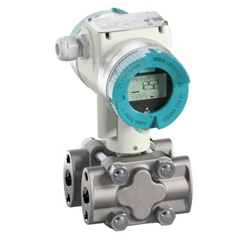
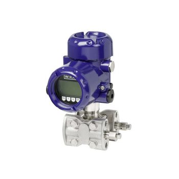
The digital pressure transmitter which features remote safety handling - developed according to IEC61508 standards for SIL2/3. Accuracy: 0,065 %
![]()
|
Datasheet
|
|
User Manual
|
The digital "high performance" pressure transmitter which features remote safety handling and is ready for digitalization - developed according to IEC61508 standards for SIL2/3. Accuracy: 0,04 %
![]()
|
Datasheet
|
|
User Manual
|
Using natural gas as a fuel for vehicles offers significant savings in fuel costs, with up to 60% savings compared to conventional fuels. Furthermore, natural gas is among the most environmentally friendly energy sources. Compared to gasoline or diesel, it causes significantly fewer emissions of unburned hydrocarbons, which are classified as harmful and potentially carcinogenic, and reduces CO2 emissions by about 20%.
This not only contributes to environmental protection but also allows vehicles powered by natural gas to gain access to zones that are closed to conventionally powered vehicles due to emission restrictions. To monitor the current level of compressed natural gas (CNG) or liquefied natural gas (LNG) in the vehicle’s tank, special measuring instruments are used. These instruments are crucial for the safety and efficiency of the operation, providing accurate data on the available fuel quantity and thus enabling optimal use of the vehicle.
- High-quality machining guarantees smooth operation with low torque and low wear
- Leak-tested tightness in accordance with BS6755 / ISO 5208 leakage rate A
- Large selection of materials and configurations available
- Customer-specific combination of valves and instruments (hook-up) on request
| Datasheet |
- Excellent load-cycle stability and shock resistance
- All stainless steel construction
- German Lloyd approva
- Scale ranges up to 0 … 1,600 bar
| Datasheet |
| User Manual |
| User Manual |
| User Manual |
| User Manual |
- One-piece design
- Laser marked for identification
- Large selection of materials and configurations available
- Customer-specific combination of adapters, fittings, valves and measuring instruments (instrument hook-up) on request
| Datasheet |
- Low-wear design due to non-rotating spindle tip in the bonnet
- Low torque and smooth operation of valve handle even at high pressure
- Enhanced safety due to blow-out proof bonnet design
- Customer-specific combination of valves and instruments (hook-up) on request
- Standardised centre distances of 37 mm and 54 mm, suitable for WIKA differential pressure gauges and commonly used process transmitters
| Datasheet |
| User Manual |
- Reliable and cost-effective
- Design per EN 837-1 or ASME B40.100
- Nominal size 40 [1 ½"], 50 [2"], 63 [2 ½"], 80 [3"], 100 [4"] and 160 [6"]
- Scale ranges to 0 ... 400 bar [0 ... 6,000 psi]
|
Datasheet |
- Very good vibration and shock resistance
- Especially robust design
- Type approval for the shipbuilding industry
- Scale ranges to 0 ... 1,000 bar or 0 ... 15,000 psi
|
Datasheet |
| User Manual |
| User Manual |
| User Manual |
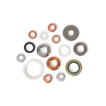
- Large selection of materials and sizes
- Versions: Flat sealing ring per EN 837-1 (and similar), WIKA sealing ring and edge sealing ring
- For process connections with/without centring spigot
|
Datasheet
|
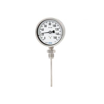
- Scale ranges from -200 ... +700 °C [-328 ... 1.292 °F]
- Fast response behaviour
- Case and stem from stainless steel
- Various connection and case mounting designs
| Datasheet |
| User Manual |
Respiratory protection devices, also known as Self-Contained Breathing Apparatus (SCBA), Compressed Air Breathing Apparatus (CABA), or simply breathing apparatus (BA), are essential equipment for individuals required to work in potentially life-threatening or harmful environments. This includes emergency services such as firefighters and rescue services, who operate in smoke-filled, toxic, or oxygen-deficient areas.
These devices are equipped with special display instruments, which are either attached directly to the valve of the breathing air cylinder or to a portable device. These displays are crucial as they provide users with an accurate reading of the remaining oxygen content in their tanks. This information is critical for knowing the remaining operational duration and to ensure there is sufficient time to either complete the task or retreat to a safe location before the oxygen supply runs out. The development and integration of advanced sensor technology into these display instruments now allows users to receive even more precise data about the oxygen supply and to activate warning signals at low oxygen levels, significantly improving safety and efficiency during operations.
- Reliable and cost-effective
- Design per EN 837-1 or ASME B40.100
- Nominal size 40 [1 ½"], 50 [2"], 63 [2 ½"], 80 [3"], 100 [4"] and 160 [6"]
- Scale ranges to 0 ... 400 bar [0 ... 6,000 psi]
|
Datasheet |
- Very good vibration and shock resistance
- Especially robust design
- Type approval for the shipbuilding industry
- Scale ranges to 0 ... 1,000 bar or 0 ... 15,000 psi
|
Datasheet |
| User Manual |
| User Manual |
| User Manual |
- Version per ISO 5171 or for acetylene per ISO 7291
- Safety features Model 111.11: With blow-out device in case back Model 111.31: With solid baffle wall (Solidfront)
- Nominal size (NS) of the case Model 111.11: NS 40, 50 and 63 Model 111.31: NS 50
- Scale ranges to 0 ... 400 bar or 0 ... 6,000 psi
| Datasheet |
| User Manual |
- Measuring ranges from 0 … 6 to 0 … 16 bar [0 ... 100 to 0 ... 200 psi] and from 0 … 200 to 0 … 400 bar [0 ... 3,000 to 0 ... 5,000 psi]
- Output signals 4 … 20 mA, DC 0 … 10 V, DC 0 … 5 V, DC 1 ... 5 V, DC 0.5 … 4.5 V ratiometric
- Oxygen clean in accordance with international standards
- Available in four levels of cleanliness
- Three packaging variants
| Datasheet |
| User Manual |
- Measuring ranges from 0 ... 6 to 0 ... 1,000 bar [0 ... 500 to 0 ... 15,000 psi]
- Current and voltage outputs
- Ingress protection IP65 or IP67
- Wetted parts and case from stainless steel
- Vacuum-tight
| Datasheet |
| User Manual |
In the gas industry, where the highest standards of safety and reliability are demanded, precisely adjustable regulators along with suitable measuring and control instruments play a crucial role in the exact regulation of gas flows.
The management of these processes is carried out using a sophisticated regulator system, supplemented by mechanical measuring instruments, switches, and transmitters. Our product range, specifically designed for such applications, is used by companies in the industrial gases sector and by producers of gas supply technology. Our offerings are particularly aimed at players in the specialty gas and chemical sector, who have a high demand for precise control and monitoring solutions to meet the stringent requirements in these specialized sectors.
- Reliable and cost-effective
- Design per EN 837-1 or ASME B40.100
- Nominal size 40 [1 ½"], 50 [2"], 63 [2 ½"], 80 [3"], 100 [4"] and 160 [6"]
- Scale ranges to 0 ... 400 bar [0 ... 6,000 psi]
|
Datasheet |
- Version per ISO 5171 or for acetylene per ISO 7291
- Safety features Model 111.11: With blow-out device in case back Model 111.31: With solid baffle wall (Solidfront)
- Nominal size (NS) of the case Model 111.11: NS 40, 50 and 63 Model 111.31: NS 50
- Scale ranges to 0 ... 400 bar or 0 ... 6,000 psi
| Datasheet |
| User Manual |
- Version with pressure connection thread in form A or form B
- 7 different setting ranges selectable
- Nominal pressures to 600 bar
- Overpressure safety up to 1,000 bar
- Vacuum protected
| Datasheet |
| Technical Informations |
- High-quality machining guarantees smooth operation with low torque and low wear
- Leak-tested tightness in accordance with BS6755 / ISO 5208 leakage rate A
- Large selection of materials and configurations available
- Customer-specific combination of valves and instruments (hook-up) on request
| Datasheet |
- Safety version with solid baffle wall designed in compliance with the requirements and test conditions of EN 837-1
- Excellent load-cycle stability and shock resistance
- Completely from stainless steel
- Scale ranges from 0 … 0.6 to 0 … 1,600 bar
|
Datasheet |
| User Manual |
| User Manual |
| User Manual |
| User Manual |
- Excellent load-cycle stability and shock resistance
- All stainless steel construction
- German Lloyd approva
- Scale ranges up to 0 … 1,600 bar
| Datasheet |
| User Manual |
| User Manual |
| User Manual |
| User Manual |
- Measuring ranges from 0 … 0.05 to 0 … 1,000 bar
- Non-linearity 0.25 % or 0.5 %
- Output 4 ... 20 mA, DC 0 ... 10 V, DC 0 ... 5 V and others
- Electrical connection: Angular connector form A and C, circular connector M12 x 1, cable outlet 2 m
- Process connection G ¼ A DIN 3852-E, ¼ NPT and others
|
Datasheet |
| User Manual |
- One-piece design
- Laser marked for identification
- Large selection of materials and configurations available
- Customer-specific combination of adapters, fittings, valves and measuring instruments (instrument hook-up) on request
| Datasheet |
A gas cylinder bundle is an arrangement of multiple gas cylinders typically used to distribute gases through a piping system. These cylinders are divided into a primary and secondary group via a valve block to ensure efficient use and continuous gas flow. Initially, gas is drawn from the primary bundle, with even distribution ensured by their parallel arrangement at a common outlet.
Once the gas volume in the primary cylinders reaches a critical minimum, a pressure transmitter enables the switch to the secondary bundle. This system allows for the exchange of the primary bundle without interrupting the gas supply. Valve blocks are used to direct the gas from a central point to multiple withdrawal points. Particularly in medical facilities, such as hospitals, these gas distribution systems are utilized for the provision of various gases, including nitrous oxide, Entonox, and oxygen. These systems are essential for maintaining a reliable and safe gas supply for different applications, including the supply to emergency facilities and operating rooms.
- Reliable and cost-effective
- Design per EN 837-1 or ASME B40.100
- Nominal size 40 [1 ½"], 50 [2"], 63 [2 ½"], 80 [3"], 100 [4"] and 160 [6"]
- Scale ranges to 0 ... 400 bar [0 ... 6,000 psi]
|
Datasheet |
- Version per ISO 5171 or for acetylene per ISO 7291
- Safety features Model 111.11: With blow-out device in case back Model 111.31: With solid baffle wall (Solidfront)
- Nominal size (NS) of the case Model 111.11: NS 40, 50 and 63 Model 111.31: NS 50
- Scale ranges to 0 ... 400 bar or 0 ... 6,000 psi
| Datasheet |
| User Manual |
- High-quality machining guarantees smooth operation with low torque and low wear
- Leak-tested tightness in accordance with BS6755 / ISO 5208 leakage rate A
- Large selection of materials and configurations available
- Customer-specific combination of valves and instruments (hook-up) on request
| Datasheet |
- Safety version with solid baffle wall designed in compliance with the requirements and test conditions of EN 837-1
- Excellent load-cycle stability and shock resistance
- Completely from stainless steel
- Scale ranges from 0 … 0.6 to 0 … 1,600 bar
|
Datasheet |
| User Manual |
| User Manual |
| User Manual |
| User Manual |
- Excellent load-cycle stability and shock resistance
- All stainless steel construction
- German Lloyd approva
- Scale ranges up to 0 … 1,600 bar
| Datasheet |
| User Manual |
| User Manual |
| User Manual |
| User Manual |
- Case and wetted parts from stainless steel
- Version per EN 837-1 or ASME B40.100
- Cost-effective and reliable
- Scale ranges from 0 ... 1 to 0 … 1,000 bar [0 ... 15 to 0 ... 15,000 psi]
|
Datasheet |
| User Manual |
| User Manual |
- Measuring ranges from 0 ... 0.1 to 0 ... 1,000 bar
- Non-linearity 0.2 % of span (BFSL)
- Output signals: 4 ... 20 mA, DC 0 ... 10 V, DC 0 ... 5 V and others
- Electrical connections: Angular connector form A, circular connector M12 x 1, various cable outlets and others
- Zero point and span adjustable via internal potentiometer
| Datasheet |
| User Manual |
- Low-wear design due to non-rotating spindle tip in the bonnet
- Low torque and smooth operation of valve handle even at high pressure
- Enhanced safety due to blow-out proof bonnet design
- Customer-specific combination of valves and instruments (hook-up) on request
- Standardised centre distances of 37 mm and 54 mm, suitable for WIKA differential pressure gauges and commonly used process transmitters
| Datasheet |
| User Manual |
The fire protection industry plays a crucial role across a wide spectrum of areas – from industrial facilities to commercial establishments, residential buildings, and building services. There are fundamentally two strategies for fire protection: One aims to reduce the oxygen content in the ambient air to a level that prevents independent fire propagation. The other method involves the use of chemical agents that react with the heat of a fire and initiate a chemical chain reaction that effectively interrupts combustion.
Gas extinguishing systems, including CO2, FM200, Novec, Inergen, and Argonite, play a pivotal role in protecting assets and human lives in various environments such as residential buildings, data centers, hospitals, hotels, parking garages, restaurants, universities, factories, and processing plants.
Manometers in these systems take on the important task of monitoring the pressure within the gas cylinders and triggering alarms when deviations from the set points occur. For use in stationary installations, certification according to VdS or LPCB is required. Mobile systems, on the other hand, are not subject to this certification requirement.
Effective monitoring and maintenance of these systems are crucial to ensure their performance and reliability. Modern fire protection systems often integrate advanced sensor technologies and automated monitoring solutions to ensure a quick response in the event of a fire and continuous efficiency in operation. This achieves optimal protection of buildings and critical infrastructures against fire and smoke, while simultaneously maximizing the safety of the people within.
- Reliable and cost-effective
- Design per EN 837-1 or ASME B40.100
- Nominal size 40 [1 ½"], 50 [2"], 63 [2 ½"], 80 [3"], 100 [4"] and 160 [6"]
- Scale ranges to 0 ... 400 bar [0 ... 6,000 psi]
|
Datasheet |
- High-quality machining guarantees smooth operation with low torque and low wear
- Leak-tested tightness in accordance with BS6755 / ISO 5208 leakage rate A
- Large selection of materials and configurations available
- Customer-specific combination of valves and instruments (hook-up) on request
| Datasheet |
- Setting ranges: 0.2 … 2 bar [3 ... 30 psi] to 30 ... 320 bar [450 ... 4,600 psi] and -0.85 ... -0.15 bar [-25 inHg ... -5 inHg]
- Non-repeatability of the switch point: ≤ 2 % of span
- Switching functions: Normally closed, normally open or change-over contact
- Media: Compressed air, neutral and self-lubricating fluids and neutral gases
| Datasheet |
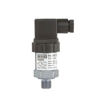
- Adjustable switch hysteresis
- Setting ranges: 0.2 … 2 bar [3 ... 30 psi] to 30 ... 320 bar [450 ... 4,600 psi] and -0.85 ... -0.15 bar [-25 inHg ... -5 inHg]
- Non-repeatability of the switch point: ≤ 2 %
- Switching functions: Normally closed, normally open or change-over contact
- Media: Compressed air, neutral and self-lubricating fluids and neutral gases
|
Datasheet
|
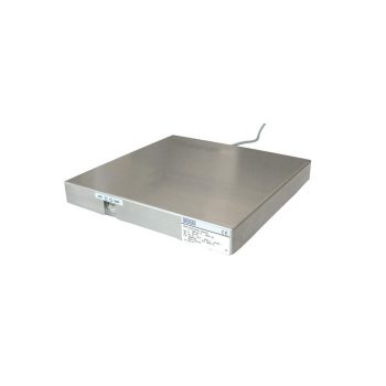
- Measuring ranges 0 … 500 kg up to 0 ... 10.000 kg
- Steel/stainless steel
- High long-term stability
- High side load tolerance
| Datasheet |
- Measuring ranges from 0 … 0.05 to 0 … 1,000 bar
- Non-linearity 0.25 % or 0.5 %
- Output 4 ... 20 mA, DC 0 ... 10 V, DC 0 ... 5 V and others
- Electrical connection: Angular connector form A and C, circular connector M12 x 1, cable outlet 2 m
- Process connection G ¼ A DIN 3852-E, ¼ NPT and others
|
Datasheet |
| User Manual |
- One-piece design
- Laser marked for identification
- Large selection of materials and configurations available
- Customer-specific combination of adapters, fittings, valves and measuring instruments (instrument hook-up) on request
| Datasheet |
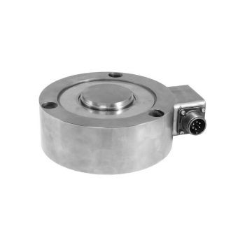
- Measuring ranges 0 ... 5 t to 0 ... 30 t
- 1,000 intervals per OIML R60 Class C
- Measuring element from stainless steel
- Hermetically sealed and welded, ingress protection IP68
| Datasheet |
| User Manual |
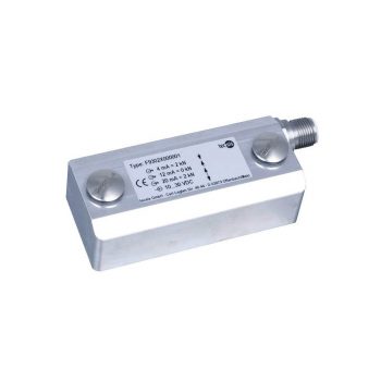
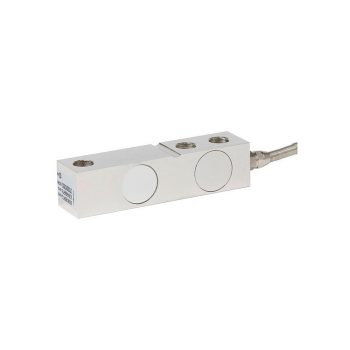
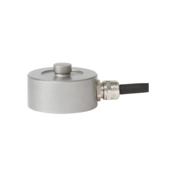
- Measuring ranges 0 ... 0.02 kN to 0 ... 2,200 kN (0 ... 5 lbs to 0 ... 500,000 lbs)
- Robust version
- Material: Stainless steel
- Ingress protection as of IP66
- Relative linearity error as of 0.1 % Fnom
| Datasheet |
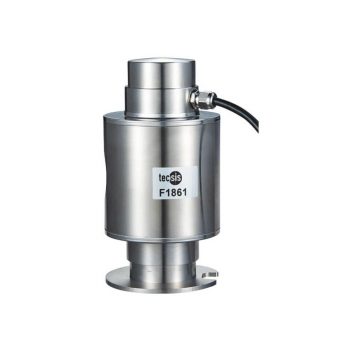
WIKA Model F1861 Compression force transducer With bilateral spherical force introduction up to 50 t
- Measuring ranges 0 ... 10 t to 0 ... 50 t
- Relative linearity error 0.03 % Fnom
- Material: Stainless steel version, IP67
- Self-centring rocker pins with dual spherical force introduction
- Adapter plates available
| Datasheet |