


 Datasheet
Benefits
- Superior signal resolution for optimum turn down ratio
- Digital signal processing with many possibilities
- Automatic reading of SENSORPROM data for easy commissioning
- User configurable operation menu with password protection
- 3 lines, 20 characters display in 11 languages
- Flow rate in various units
- Totalizer for forward, reverse and net flow as well as additional information available
- Multiple functional outputs for process control, minimum configuration with analogue, pulse/frequency and relay output (status, flow direction, limits)
- Comprehensive self-diagnostic for error indication and error logging (see SITRANS F M diagnostics)
- Batch control (MAG 6000 only)
- Custody transfer approval: MI-001 for cold water, PTB K 7.2 and OE12/C 040 for chilled water
- MAG 6000 with add-on bus modules for HART, FOUNDATION Fieldbus H1, DeviceNet, Modbus RTU/RS485, PROFIBUS PA and DP
Application
The SITRANS F M flowmeters are suitable for measuring the flow of almost all electrically conductive liquids, pastes and slurries. The main applications can be found in:
- Water and waste water
- Chemical and pharmaceutical industries
- Food and beverage industries
- Power generation and utility
Design
The transmitter is designed as either IP67 NEMA 4X/6 enclosure for compact or wall mounting or 19″ version as a 19″ insert as a base to be used in:
- 19″ rack systems
- Front panel mounting IP65/NEMA 2
- Panel mounting IP20/NEMA 1
- Wall mounting IP66/NEMA 4X
Several options on 19″ versions are available such as:
- Transmitters mounted in safe area for Ex ATEX approved flow sensors (incl. barriers)
- Transmitters with electrode cleaning unit on request
Function
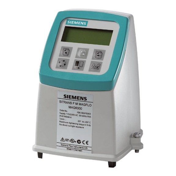
The MAG 5000/6000 are transmitters with a built-in alphanumeric display in several languages. The transmitters evaluate the signals from the associated electromagnetic sensors and also fulfil the task of a power supply unit which provides the magnet coils with a constant current.
Further information on connection, mode of operation and installation can be found in the data sheets for the sensors.
Displays and controls
Operation of the transmitter can be carried out using:
- Control and display unit
- HART communicator
- PC/laptop and SIMATIC PDM software via HART communication
- PC/laptop and SIMATIC PDM software using PROFIBUS or Modbus communication
Technical specifications
|
Mode of operation and design |
|
|
Measuring principle |
Electromagnetic with pulsed constant field |
|
Empty pipe |
Detection of empty pipe (special cable required in remote mounted installation) |
|
Excitation frequency |
Depend on sensor size |
|
Electrode input impedance |
> 1 x 10¹⁴ Ω |
|
Input |
|
|
Digital input |
11 … 30 V DC, Ri = 4. 4 KΩ |
|
50 ms |
|
I11 V DC = 2.5 mA, I30 V DC = 7 mA |
|
Output |
|
|
Current output |
|
|
0 … 20 mA or 4 … 20 mA |
|
< 800 Ω |
|
0.1 … 30 s, adjustable |
|
Digital output |
|
|
0 … 10 kHz, 50 % duty cycle (uni/bidirectional) |
|
24 V DC, 30 mA, 1 kΩ ≤ Ri ≤ 10 kΩ, short-circuit-protected (power supplied from flowmeter) |
|
3 … 30 V DC, max. 110 mA, 200 Ω ≤ Ri ≤ 10 kΩ powered from connected equipment) |
|
0.1 … 30 s, adjustable |
|
Relay output |
|
|
Changeover relay, same as current output |
|
42 V AC/2 A, 24 V DC/1 A |
|
Low flow cut off |
0 … 9.9 % of maximum flow |
|
Galvanic isolation |
All inputs and outputs are galvanically isolated |
|
Max. measuring error (incl. sensor and zero point) (for detailed accuracy specifications see “System information”) |
|
|
± 0.4 % ± 1 mm/s |
|
± 0.2 % ± 1 mm/s |
|
Rated operation conditions |
|
|
Ambient temperature |
|
|
|
|
-40 … +70 C (-40 … +158 F°) |
|
Mechanical load (vibration) |
|
|
Compact version |
18 … 1000 Hz, 3.17 g RMS, sinusoidal in all directions to IEC 68-2-36 |
|
19“ insert |
1 … 800 Hz, 1 G, sinusoidal in all directions to IEC 68-2-36 |
|
Degree of protection |
|
|
Compact version |
IP67/NEMA 4X/6 to IEC 529 and DIN 40050 (1 mH2O 30 min.) |
|
19“ insert |
IP20/NEMA 1 to IEC 529 and DIN 40050 |
|
EMC performance |
IEC/EN 61326-1 (all environments) IEC/EN 61326-2-5 |
|
Display and keypad |
|
|
Totalizer |
Two eight-digit counters for forward, net or reverse flow |
|
Display |
Background illumination with alphanumeric text, 3 x 20 characters to indicate flow rate, totalized values, settings and faults; Reverse flow indicated by negative sign |
|
Time constant |
Time constant as current output time constant |
|
Design |
|
|
Enclosure material |
|
|
Fiber glass reinforced polyamide; stainless steel AISI 316/1.4436 (IP65) |
|
Standard 19“ insert of aluminium/steel (DIN 41494), width: 21 TE, height: 3 HE |
|
IP20/NEMA 1; Aluminium |
|
IP20/NEMA 1 (prepared for IP65/NEMA 2 display side); ABS plastic |
|
IP66/NEMA 4X; ABS plastic |
|
Dimensions |
|
|
See dimensional drawings |
|
See dimensional drawings |
|
Weight |
|
|
0.75 kg (2 lbs) |
|
See dimensional drawings |
|
Power supply |
|
|
Power consumption |
IST= 4 A (250 ms): |
|
Certificates and approvals |
|
|
General purpose |
|
|
Hazardous area |
|
|
Custody transfer |
|
|
Marine |
|
|
Others |
|
|
Communication |
|
|
Standard |
|
|
HART 5.2 optional |
|
Optional as add-on modules
|