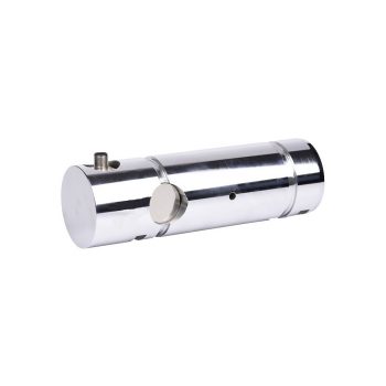
• Measuring ranges 0 ... 5 kN up to 0 ... 10,000 kN
  • Corrosion-resistant stainless steel design
  • Existing non-measuring bolts are simply replaced by the measuring axes
  • For overload protection in cranes and hoists
  • Good reproducibility, simple installation
Datasheet

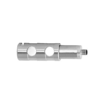
  • Measuring ranges 0 ... 5 kN to 0 ... 200 kN [0 ... 1,124 lbf to 0... 44,962 lbf]
  • Stainless steel version (corrosion-resistant)
  • Integrated amplifier
  • High long-term stability, high shock and vibration resistance
  • Good reproducibility, simple installation
Datasheet
User Manual

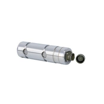
  • Measuring ranges from 0 ... 10 kN [from 0 ... 2,248 lbf]
  • Stainless steel version (corrosion-resistant)
  • Integrated amplifier
  • High long-term stability, high shock and vibration resistance
  • Good reproducibility, simple installation
Datasheet
User Manual


WIKA Load Pins – Integrated Force Measurement Axles & Load Measuring Bolts

Load pins from WIKA (also called load measuring pins, force measuring axles or load bolts) are special force transducers designed to replace existing structural bolts in machines or lifting systems. Installed directly in the force flow, they measure the acting load in real time — ideal for cranes, hoists, winches, sheaves, lifting gear and a wide range of industrial machinery where space is limited and direct integration is required.

WIKA load pins cover small measuring ranges (e.g., 0 … 5 kN) up to heavy-duty models capable of measuring forces of 20 … 10,000 kN. They are made from corrosion-resistant CrNi stainless steel and use thin-film technology or strain gauges. Common output signals include 4–20 mA, 0–10 V and CANopen®.


FAQ About WIKA Load Pins

Answers regarding operation, selection, installation, output signals and typical applications.

What is a load pin?

A load pin is a force sensor designed in the shape of a bolt or axle. It replaces a standard bearing, hinge, or support pin and measures the tensile or compressive load acting on the structure.

How does a WIKA load pin work?

The pin contains thin-film sensors or strain gauges. When a force acts on the pin, it causes a slight deformation that changes the sensor’s electrical resistance. Electronics inside the load pin convert this into a standardized output signal.

Where are load pins typically used?

Typical applications include cranes, lifting systems, winches, sheaves, construction machinery, marine and offshore equipment, industrial automation and anywhere forces need to be measured directly in the load path.

What measuring ranges are available?

Standard WIKA load pins range from 0 … 5 kN up to 0 … 200 kN. Heavy-duty versions reach 20 … 10,000 kN depending on the design.

What materials and construction quality do WIKA load pins offer?

Load pins are made from high-strength, corrosion-resistant CrNi stainless steel (e.g. 1.4542). They are built for long-term stability, high shock and vibration resistance, and reliable operation in harsh environments.

Which output signals are supported?

Common outputs include 4–20 mA, 0–10 V, dual redundant outputs (for safety-related systems), and digital interfaces such as CANopen®.

What should be considered during mechanical installation?

The load pin directly replaces an existing mechanical pin. Proper alignment in the axial direction is essential, and bending or lateral forces should be minimized to ensure accurate measurement.

Are there certified or safety-approved versions?

Yes — some WIKA load pin series (e.g. F53 family) are DNV certified for offshore and shipboard use. Variants for ATEX/Ex zones are also available. These certifications make load pins suitable for safety-critical lifting applications.

What advantages do load pins offer compared to standard load cells?

Load pins allow direct integration without major modifications, making them ideal for retrofitting. They require minimal installation space and measure the force directly where it occurs.

How are load pins calibrated?

Calibration is performed using known test loads, verifying linearity, repeatability and documenting results. For best accuracy, calibration should consider the final installed condition.

How can I request a quotation?

Provide ICS Schneider with application details such as required load range, bolt dimensions, installation environment, and preferred output signal. You can also add the product to the inquiry list on the website.

Diese Website benutzt Cookies. Wenn du die Website weiter nutzt, gehen wir von deinem Einverständnis aus.