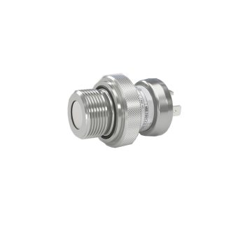
- nominal pressure: 0 ... 100 mbar up to 0 ... 40 bar
- accuracy: 0.35 % (opt. 0.25% / 0.1 %) FSO
- small thermal effect
- excellent long term stability
- pressure port G 3/4" flush
 Datasheet Datasheet |
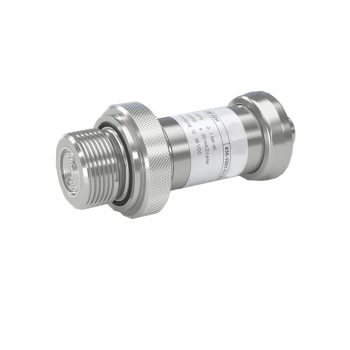
- nominal pressure: 0 ... 400 mbar up to 0 ... 40 bar
- accuracy: 0.1 % FSO
- thermal error in compensated range -20 … 80 °C: 0.2 % FSO TC 0.02 % FSO / 10 K
- turn-down 1:10
- communication interface for adjusting of offset, span and damping
| Datasheet |
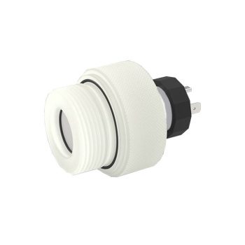
- nominal pressure: 0 ... 400 mbar up to 0 ... 60 bar
- accuracy: 0.5 % FSO
- pressure port G 3/4" flush
| Datasheet |
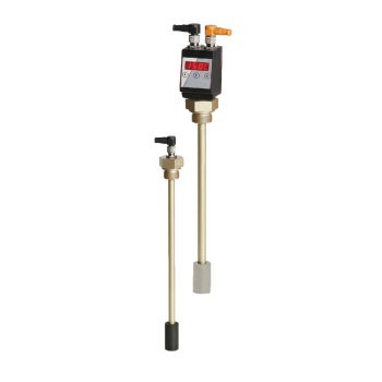
- nominal pressure: 0 ... 40 mbar up to 0 ... 20 bar
- accuracy: 0.35 % (opt. 0.25 %) FSO
- pressure port G 1 1/2" for pasty and polluted media
| Datasheet |
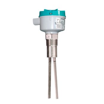
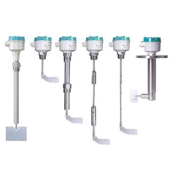
- High resistance to mechanical forces
- Strong vibration resistance to high bulk material loads
- Rotatable enclosure
- Suitable for low density material: standard version, 20 g/l (1.3 lb/ft³); liquid/solid interface version, 50 g/l (3 lb/ft³), and low density option min. 5 g/l (0.3 lb/ft³)
- Customer desired extensions up to 20 000 mm (787”)
- Optional detection of solids within liquid
- Durable short fork option with 165 mm (6.5 inch) insertion length
![]()
|
Datasheet
|
|
User Manual
|
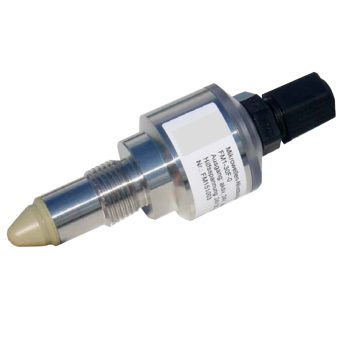
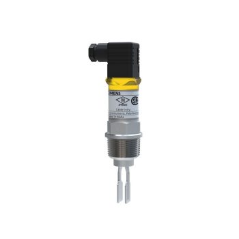
- Testfunktion einschließlich Remoteoptionen
- Fehlerüberwachung auf Korrosion, Ausfall der Schwingung oder Leitungsbruch zum Piezoantrieb
- Kompakte Bauweise
- Geringe Eintauchtiefe ab 40 mm (1.57")
- Optionen für extreme Drücke und Temperaturen
![]()
|
Datasheet
|
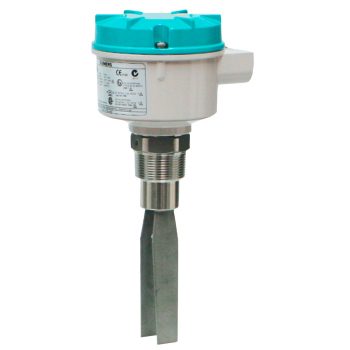
- Ease of setup with no calibration and rotatable enclosure
- Suitable for low bulk density materials starting at 30 g/l (1.9 lb/ft³)
- Adjustable sensitivity for varied applications
![]()
|
Datasheet
|
|
User Manual
|
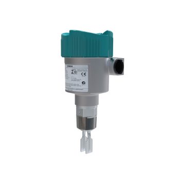
SITRANS LVL100 is a compact vibrating level switch for liquid and slurry applications such as overflow, high, and low level detection. Also ideal for pump protection, safety backup and confined spaces.
|
Datasheet
|
|
User Manual
|
SITRANS LPS200 is a rotary paddle switch for point level detection in bulk solids. Ideal for point level or safety backup applications with SIL 2 and motor failsafe detection.
![]()
|
Datasheet
|
|
User Manual
|