


The 200ADM-P is a current injection system with a wide range of advanced features including phase shift, data storage and harmonic analysis.
- 0-200A output current
- True RMS metering with 1 cycle capture
- Variable auxiliary ac voltage/ current output with phase shift
- Auxiliary metering input V, f, Φ, Z, P, S, PF, CT ratio, harmonics & more
- Variable auxiliary output 12-220Vdc
- Multi-function auto-ranging timing system
- Current limit mode for fine control
- Data storage to USB memory key including waveform & harmonics USB keyboard/printer interface
- Automatic mains voltage selection
 Datasheet Datasheet
|
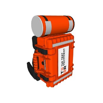
- 0-50A output current
- True RMS metering with 1 cycle capture
- Variable auxiliary AC voltage/current output with phase shift
- Auxiliary metering input V, f, φ, Z, P, S, PF, CT ratio, harmonics
- Variable auxiliary output 12-220VDC
- Multi-function auto-range timing system
- Current limit mode for fine control
- Data storage to USB memory key including waveform & harmonics
- USB keyboard interface
- Automatic mains voltage selection
- Optional Backpack System
|
Datasheet
|

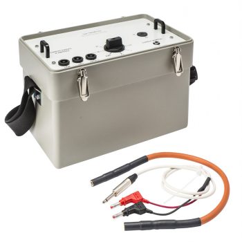
- 0-100A output current
- True RMS metering with single cycle capture
- Auxiliary DC and AC output
- Multi-function auto-ranging timing system
- Current limit mode for fine control
- Automatic mains voltage selection
- Thermal and over-current protection
|
Datasheet
|
- 0-100A output current
- True RMS metering with single cycle capture
- Auxiliary DC and AC output
- Multi-function auto-ranging timing system
- Current limit mode for fine control
- Automatic mains voltage selection
- Thermal and over-current protection
|
Datasheet
|

- 0.5 ohms to 1666.5 ohms in 8 steps
- Maximum current 0.2-10A
- Improves current control into low impedance loads
- Particularly suitable for solid state relays
- Can be used as swamping impedance for non-linear loads
- Thermal cut out
- Forces test current to a sinusoid
- Improves timing accuracy when testing electro-mechanical relays
- 0.25A – 100A ranges
- High overload capability
- 50/60Hz operating frequency
- High efficiency

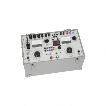
- 0-50A three phase output
- Clear and simple user interface
- 3 phase current output
- 0-50A per phase output current
- True RMS digital metering
- Memory ammeter
- Multi-function timing system
- Auxiliary metering input
- Large back-lit liquid crystal display
- Thermal and over-current protection
- Compact and portable
- 220V or 400V 3 phase mains supply options
- 115V-440V 3 wire supply with optional supply transformer
|
Datasheet
|
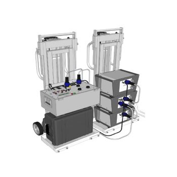
- Clear and simple user interface
- 3-Φ current output
- 0-1200A per phase output current
- True RMS digital metering
- Memory ammeter
- Multi-function timing system
- Auxiliary metering input
- Large back-lit liquid crystal display
- Thermal and over-current protection
- Portable on battery powered stair climbing trolleys
- Maximum power output 13kVA
|
Datasheet
|
