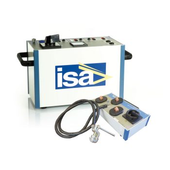
The Line impedance kit is composed of two modules, STLG and STSG. The kit is meant to be used with STS 5000, STS 4000 and eKAM in order to perform Line Impedance test.

Datasheet


Line Impedance Testing

Line impedance testing covers measurement and evaluation of the electrical impedance of lines and cables in power systems and industrial networks. Line impedance — consisting of resistance and reactance, and in some cases capacitive components — is essential for short-circuit current calculation, protection relay setting, fault location and voltage drop assessment. By injecting defined test currents or voltages and analysing voltage drop and phase angle, the real line parameters can be determined under representative conditions.

FAQ

What is line impedance?

Line impedance is the complex sum of a line’s resistance and its inductive and capacitive components. It defines how currents and voltages behave along the line during normal operation and in fault conditions.

Why is line impedance testing important?

Accurate impedance values are required for correct short-circuit current calculations, relay settings, tripping times and voltage drop estimates. Differences between design values and real impedance may cause mal-coordination of protection and loss of selectivity.

Where is line impedance testing used?

Typical applications include short-circuit studies, protection coordination, verification of network models, fault location on overhead lines and cables, voltage drop analysis and evaluation of network extensions or modifications.

How does line impedance testing work in principle?

A defined test current or voltage is applied to the line. From the measured voltage drop and the phase relation between current and voltage, the complex impedance (magnitude and angle) is calculated.

Which parameters are usually measured?

Resistance R, reactance X, impedance magnitude |Z|, phase angle, and — if required — positive-, negative- and zero-sequence impedances or per-unit-length parameters (r, x, l).

What is the difference between resistance and impedance?

Resistance represents only the ohmic component. Impedance includes both resistive and reactive components and is therefore the relevant parameter for AC systems and short-circuit calculations.

Can line impedance testing be done on energized systems?

Depending on the method, small test signals can be superimposed on the operating network, allowing measurements without interrupting supply. Other methods require de-energized lines and defined test setups.

Why does frequency matter?

Impedance is frequency-dependent. Tests are usually performed close to system frequency to represent actual operating conditions; special applications may use different frequencies for diagnostic purposes.

How are measurement results evaluated?

The measured impedance is compared with design data or calculated values. Significant deviations indicate incorrect network data, unnoticed line changes or possible defects.

What is the impact of line impedance on protection relays?

Protection relays use line impedance and short-circuit currents to define operating zones and characteristics. Incorrect impedance data may lead to under-reach or over-reach and affect selectivity and safety.

Can line impedance testing support fault location?

Yes. With known impedance parameters, measured voltages and currents can be used to estimate fault distance. Accurate impedance data improves the performance of distance protection and fault-location algorithms.

When should line impedance tests be performed?

Typical cases are commissioning of new lines, after network modifications or cable replacement, when protection settings are revised, or when measured operating values do not match system calculations.

Who should perform line impedance testing?

Qualified engineers or technicians experienced in power system analysis, protection engineering and high/medium-voltage installations, familiar with test methods, safety rules and interpretation of complex impedance values.

Which safety aspects must be considered?

Depending on the method: correct isolation or defined operating conditions, application of earthing and switching rules, safe test setups, suitable test leads and personal protective equipment. Test procedures must be clearly defined and documented.

How should results be documented?

In test reports including line data, test method, measuring points, impedance values, date and tester. These reports form the basis for network models, protection settings and future comparison measurements.

Which typical fault patterns can be derived from impedance measurements?

High impedance may indicate poor connections, partial breaks or corrosion; lower-than-expected impedance can point to parallel paths, unintended connections or model inaccuracies.

Diese Website benutzt Cookies. Wenn du die Website weiter nutzt, gehen wir von deinem Einverständnis aus.