


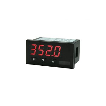
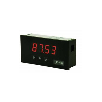
| Housing | 48 x 24 mm |
| Display | 4-digit 10 mm digit height Colour: red, green, orange or blue display |
| Range displayed | -1999 to 9999 |
| Operation | front panel keyboard protection class IP65 |
| Input | Potentiometer 0…100% span >1 kOhm….<1000 kOhm |
| Analogue Output | – |
| Switch point | – |
| Interface | – |
| Power supply | 24 VDC +/-10% galvanic isolated Other voltage supplies on demand! |
| Sensor supply | – |
| Software properties |
|
 Datasheet Datasheet
|
|
User Manual
|
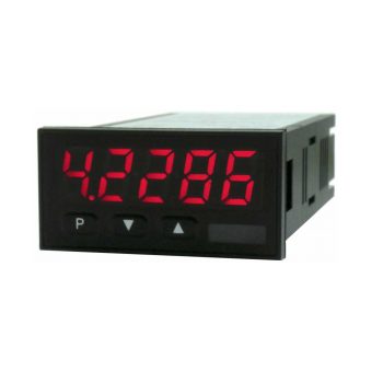
| Housing | 48 x 24 mm |
| Display | 5-digit 10 mm digit height Colour: red, green, orange or blue display |
| Range displayed | -19999 to 99999 |
| Operation | front panel keyboard protection class IP65 |
| Input | Potentiometer >1 kOhm to <1000 kOhm Digital input: <2.4V OFF, >10V ON, max. 30 VDC |
| Analogue Output | 0/4-20 mA / 0-10 VDC / 16 Bit Alternatively digital input |
| Switch point | 2 PhotoMos outputs (NOC) 30 VDC/AC, 0.4 A |
| Interface | – |
| Power supply | 24 VDC galvanic isolated 100-240 VAC 50/60 Hz / DC +/- 10% |
| Sensor supply | – |
| Software properties |
|
|
Datasheet
|
|
User Manual
|
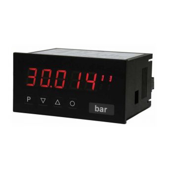
| Housing | 72 x 36 mm |
| Display | 4-digit 14 mm digit height Colour: red, green, orange or blue display |
| Range displayed | -1999 to 9999 |
| Operation | front panel keyboard protection class IP65 |
| Input | Potentiometer 0…100% span >1 kOhm….<1000 kOhm |
| Analogue Output | – |
| Switch point | 2 relays (change-over contact) 250 V / 5 AAC, 30 V / 5 ADC |
| Interface | – |
| Power supply | 230 VAC 24 VDC +/-10% galvanic isolated Other voltage supplies on demand! |
| Sensor supply | – |
| Software properties |
|
|
Datasheet
|
|
User Manual
|
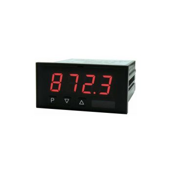
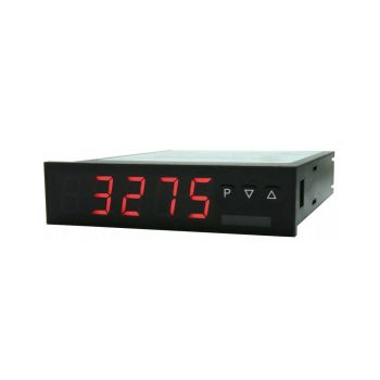
| Housing | 96 x 24 mm |
| Display | 4-digit 14 mm digit height Colour: red, green, orange or blue display |
| Range displayed | -1999 to 9999 |
| Operation | front panel keyboard protection class IP65 |
| Input | Potentiometer 0…100% span >1 kOhm….<1000 kOhm |
| Analogue Output | – |
| Switch point | – |
| Interface | – |
| Power supply | 230 VAC 24 VDC +/-10% galvanic isolated Other voltage supplies on demand! |
| Sensor supply | – |
| Software properties |
|
|
Datasheet
|
|
User Manual
|
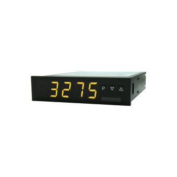
| Housing | 96 x 24 mm |
| Display | 5-digit 14 mm digit height Colour: red, green, orange or blue display |
| Range displayed | -19999 to 99999 |
| Operation | front panel keyboard protection class IP65 |
| Input | Potentiometer >1 kOhm to <1000 kOhm |
| Analogue Output | 0/4-20 mA / 0-10 VDC / 16 Bit Alternatively interface RS232/RS485 |
| Switch point | 1 or 2 change-over relays 250 VAC / 2 AAC ; 30 VDC / 2 ADC |
| Interface | RS232 or RS485 galvanic isolated Alternatively analog output |
| Power supply | 10-40 VDC / 18-30 VAC 50/60Hz 100-240 VAC 50/60 Hz / DC +/- 10% |
| Sensor supply | – |
| Software properties |
|
|
Datasheet
|
|
User Manual
|
| Housing | 96 x 48 mm |
| Display | 4-digit 14 mm digit height Colour: red, green, orange or blue display |
| Range displayed | -1999 to 9999 |
| Operation | front panel keyboard protection class IP65 |
| Input | Potentiometer 0…100% span >1 kOhm….<1000 kOhm |
| Analogue Output | – |
| Switch point | – |
| Interface | – |
| Power supply | 230 VAC 24 VDC +/-10% galvanic isolated Other voltage supplies on demand! |
| Sensor supply | – |
| Software properties |
|
|
Datasheet
|
|
User Manual
|
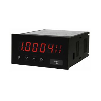
| Housing | 96 x 48 mm |
| Display | 5-digit 14 mm digit height Colour: red, green, orange or blue display |
| Range displayed | -19999 to 99999 |
| Operation | front panel keyboard protection class IP65 |
| Input | Potentiometer 0…100% span >1kOhm….<1000kOhm Digital input: <2.4V OFF, >10V ON, max. 30 VDC |
| Analogue Output | 0/4-20 mA / 0-10 VDC / 16 Bit Alternatively digital input |
| Switch point | 2 relays (change-over contact) 250 V / 5 AAC, 30 V / 5 ADC |
| Interface | – |
| Power supply | 230 VAC 10-30 VDC galvanic isolated Other voltage supplies on demand! |
| Sensor supply | – |
| Software properties |
|
|
Datasheet
|
|
User Manual
|
| Housing | 96 x 48 mm |
| Display | 5-digit 14 mm digit height Colour: red, green, orange or blue display |
| Range displayed | -19999 to 99999 |
| Operation | front panel keyboard protection class IP65 |
| Input | Potentiometer >1 kOhm to <1000 kOhm Digital input: <2.4V OFF, >10V ON, max. 30 VDC |
| Analogue Output | 2 analog outputs 0/4-20 mA / 0-10 VDC / 16 Bit |
| Switch point | 2 or 4 relays (change-over contacts) 250 V / 5 AAC, 30 V / 5 ADC or 8 PhotoMos outputs (NOC) 30 V / 0.4 A AC/DC |
| Interface | RS232 or RS485 galvanic isolated Alternatively to analog output 2 |
| Power supply | 100-240 VAC 50/60 Hz / DC +/- 10% 10-40 VDC / 18-30 VAC 50/60Hz |
| Sensor supply | – |
| Software properties |
|
|
Datasheet
|
|
User Manual
|
