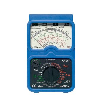
Specifications:
- DC voltage: 100 mV to 600 V (8 ranges)
- Accuracy: 1.5% except with 100 mV range (2.5%)
- AC voltage: 10 V to 600 V (5 ranges) Bandwidth: [20Hz-100kHz] on 10 V range, [20Hz-1kHz] on 300 V and 1,000 V ranges Accuracy: 2.5% except with 100 mV range (3%)
- Impedance: 20 kΩ/V
- DC current: 50 µA to 5 A (5 ranges)
- AC current: 5 mA to 5 A (4 ranges) Bandwidth: [40 Hz-5 kHz] Accuracy: 2.5% except with 5 A range(5%)
- Resistance: 10 kΩ and 1 MΩ
- Audible continuity test: R < 50 Ω
- dB scale (V AC).
- Fuse status LED
- Dimensions: 160 x 105 x 56 mm
- Weight: 500 g
- Use on any installation rated lower than or equal to CAT III 600 V asper IEC/EN 61010-1 Edition 2
 Datasheet Datasheet
|
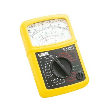
Specifications:
- DC voltage: 100 mV to 600 V (8 ranges)
- AC voltage: 10 V to 600 V (5 ranges)
- DC current: 50 µA to 15 A (7 ranges)
- AC current: 1.5 mA to 15 A (5 ranges)
- Automatic calibration
- “Voltest” LED if voltage present in ohmmeter mode
- Typical accuracy: 1.5%
- Impedance: 20 kΩ/V
- Resistance: 10 kΩ and 1 MΩ
- Audible continuity test: R < 50 Ω
- dB scale (AC voltages)
- Fuse status LED
- Dimensions: 160 x 105 x 56 mm
- Weight: 500 g
- IP53
- Use on any installation rated lower than or equal to CAT III 600 V asper IEC/EN 61010-1 Edition 2
|
Datasheet
|
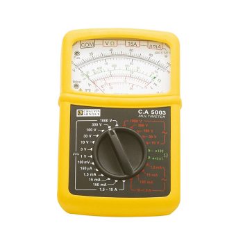
Specifications:
- DC voltage: 100 mV to 600 V (8 ranges)
- AC voltage: 10 V to 600 V (5 ranges)
- DC current: 50 µA to 10 A (6 ranges)
- AC current: 3 A to 240 A (5 ranges) with MN89clamp supplied
- Automatic calibration
- “Voltest” LED if voltage present in ohmmeter mode
- Typical accuracy: 1.5%
- Impedance: 20 kΩ/V
- Resistance: 10 kΩ and 1 MΩ
- Audible continuity test: R < 50 Ω
- dB scale (AC voltages)
- Fuse status LED
- Dimensions: 160 x 105 x 56 mm
- Weight: 500 g
- IP53
- Use on any installation rated lower than or equal to CAT III 600 V as per IEC/EN 61010-1 Edition 2
|
Datasheet
|
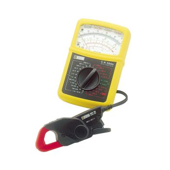
Specifications:
- Automatic recognition of AC/DC
- AC/DC voltage: 400 mV to 600 V (5 ranges)
- Operating frequency: 20Hz to 10 kHz
- Typical accuracy: 0.5% -Impedance: 10 MΩ
- AC/DC current: 400 µA to 10 A (6 ranges)
- Resistance: 400 Ω to 40M Ω(6 ranges)
- Continuity test: (R< 400 Ω) and diode test
- Frequency: 4 kHz to 400 kHz(3 ranges)
- Reading of dB scale from -20 to16 dB
- Fuse status LED
- "Voltest"LED if a voltage is present in ohmmeter and continuity modes
- Max and Hold functions
- Can be used as a zero galvanometer
- Backlighting
- Dimensions: 160 x 105 x 56 mm
- Weight: 500g
- Use on any installation rated lower than or equal to CAT III 600 V as per IEC/EN 61010-1 Edition 2
|
Datasheet
|