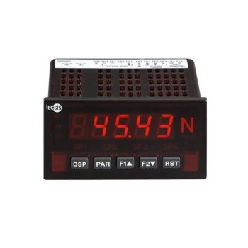
- 5-digit digital display, easy to read up to 50 m
- High accuracy: 0.02 % of reading +3 μV
- Extensive functions easy to set on the instrument or via PC
- Plug-in expansion cards, analogue output, 2 or 4 limit values, serial interface
- Ingress protection IP65
 Datasheet Datasheet |
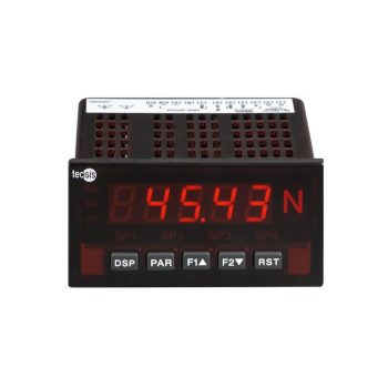
- 5-digit digital display, easy to read up to 50 m
- High accuracy: 0.03 % of reading +2 μA or +2 mV
- Extensive functions easy to set on the instrument or via PC
- Plug-in expansion cards, analogue output, 2 or 4 limit values, serial interface
- Ingress protection IP65
| Datasheet |
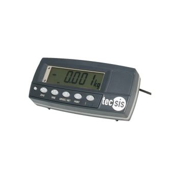
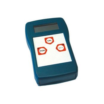
- 6-digit liquid crystal display (LCD) with backlighting
- Extensive functions easy to set on the instrument or via PC
- International approval for applications requiring verified measurements OIML, NTEP
- AC, DC (DC 7 ... 24 V) operating on (rechargeable) battery power (DC 4.8 ... 24 V) – ideal for a number of mobile applications
- High ingress protection, IP65
| Datasheet |