


- High Current Output Leads
- Designed for PCU1-SP Mk2 + NAL2000
- Copper bar terminations
- 2000A Rating
- 1.5m long
- High Current Output Leads
- Designed for PCU1-SP Mk2 + NAL2000
- Copper bar terminations
- 2000A Rating
- 3m long
- High Current Output Leads
- Designed for PCU1-SP Mk2 + NAL2000
- Copper bar terminations
- 2000A Rating
- 5m long
- High Current Output Leads
- Designed for PCU1-SP Mk2 + NAL5000
- Copper bar terminations
- 5000A Rating
- 2m long
- High Current Output Leads
- Designed for PCU1-SP Mk2 + NAL5000
- Copper bar terminations
- 5000A Rating
- 3m lon

- Exceptional versatility and reliability
- Two output taps for a wide range of load impedances
- Configurable maximum current: 200A on the 60V range or 100A on the 120V range
- Seamless connection to the Control Unit with included interconnect lead
- Designed to meet the stringent requirements of BS EN61010
- Duty cycle trip and thermal protection for enhanced safety
- Exceptional versatility and reliability
- Three output taps for a wide range of load impedances
- Configurable maximum current: 2000A on the 4V range, 1000A on the 8V range or 500A on the 16V range
- Seamless connection to the Control Unit with included interconnect lead
- Designed to meet the stringent requirements of BS EN61010
- Duty cycle trip and thermal protection for enhanced safety

- Exceptional versatility and reliability
- Three output taps for a wide range of load impedances
- Configurable maximum current: 5000A on the 2.3V range, 2500A on the 4.6V range or 1250A on the 9.2V range
- Seamless connection to the Control Unit with included interconnect lead
- Designed to meet the stringent requirements of BS EN61010
- Duty cycle trip and thermal protection for enhanced safety

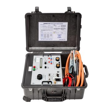
- Primary current injection up to 750A
- 4V output
- 16V 40A output for secondary injection
- True RMS digital metering with single cycle capture
- Data storage to USB memory key including waveform & harmonics
- Multi-function timing system
- Large back-lit liquid crystal display
- Thermal and over-current protection
- Automatic switch-off at end of test
- Compact and portable
- Automatic mains voltage selection
- Clear and simple user interface
- Available in Metal or Pelican case
 Datasheet Datasheet |
| User Manual |

The PCU1-SP Mk3 is a versatile primary current injection test system, ideal for stability and circuit breaker testing, with direct-reading CT ratio and polarity tests.
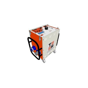
- 5kA maximum output current (higher overload currents for 2s)
- Multi-function digital timing system
- Digital true RMS memory ammeter
- Solid state switching
- 200A, 2000A and 5000A loading units
- Three range outputs on NLU2000 & NLU5000 Loading Units
- Rugged, compact design
- Optional trolley mounting of system
- Secondary injection up to 100A
- Auxiliary metering input
- Direct reading CT ratio and polarity
| Datasheet |
| User Manual |
- Primary injection up to 750A
- 4V output*
- 16V 40A output for secondary injection
- True RMS memory ammeter with single cycle capture
- Multi-function timing system
- Large back-lit liquid crystal display
- Thermal and over-current protection
- Automatic switch-off at end of test
- Compact and portable
- Automatic mains voltage selection*
|
Datasheet
|
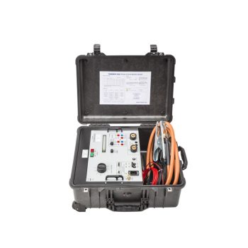
- Primary injection up to 750A
- 4V output
- 16V 40A output for secondary injection
- True RMS digital metering with single cycle capture
- Multi-function timing system
- Large back-lit liquid crystal display
- Thermal and over-current protection
- Automatic switch-off at end of test
- Compact and portable
- Automatic mains voltage selection
- Clear and simple user interface
|
Datasheet
|

- 5kA maximum output current (higher overload currents for 2s)
- Multi-function digital timing system
- Digital true RMS memory ammeter
- Solid state switching
- 200A, 2000A and 5000A loading units
- Three range outputs on loading units
- Rugged, compact design
- Optional trolley mounting of system
- Secondary injection up to 100A
- Auxiliary metering input
-
Direct reading CT ratio and polarity
|
Datasheet
|
