
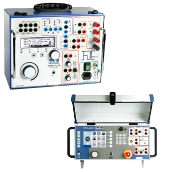
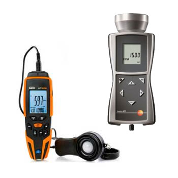
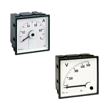
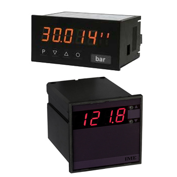



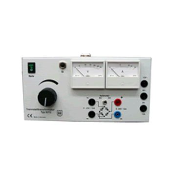
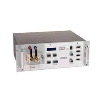
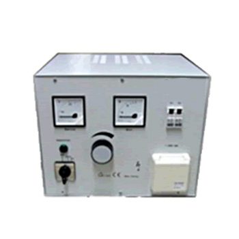
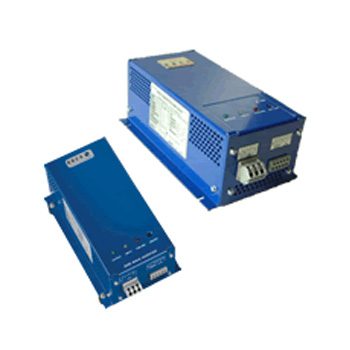




























TDMS 7 is a powerful software package providing data management for acceptance and maintenance testing activities. Electrical apparatus data and test results are saved in the TDMS 7 database for historical results analysis. TDMS 7 software organizes test data and results for the majority of electrical apparatus tested with ISA test sets and related software.
Datenblatt
|
.
.
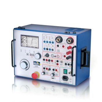
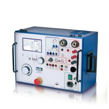
- Multi function system for testing: current, voltage and power transformers
- Current transformer excitation, ratio and polarity test set
- Primary injection testing capabilities
- 3000 V AC high-pot test
- Generates up to 800 A (option up to 4000A with high current booster)
- Microhmmeter function (option) up to 400A DC
- RS232 interface for pc connection
- Test results and settings are saved into local memory
- Compact and lightweight
Datasheet
|
- Multi function primary test system for testing substation equipment such as: current, voltage and power transformers, all type of protection relays, energy meters and transducers
- Primary injection testing capabilities
- 3000 V AC high-pot test
- Generates up to 800 A (option up to 4000A with high current booster)
- Microhmmeter function (option): up to 400A DC
- RS232 interface for pc connection
- Possibility to store test results in T 3000 local memory (up to 500 results)
- Compact and lightweight.
Datasheet |
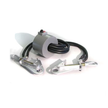
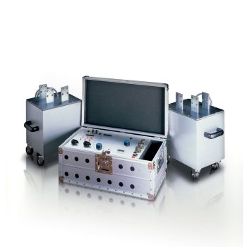
- Maximum current up to 4000 A
- Designed to avoid the power losses due to long cables connections
- Connected to T 2000 or T 3000 unit with long (up to 20 m) low power control cable
- Supplied with high current clamps and high current cables
- Fully automatic
- Two portable units: control and current units
- High current output: up to 2000 A, 3000 A and 5000 A
- Variable output frequency: 15 - 500 Hz
- CT ratio, burden and polarity test
- Large graphic display
- Advanced Test & Data Management Software for test set control, results storage and analysis
- Step & touch plus ground resistance tests with STLG option
- Reduced timing test
- USB interface and Ethernet interface for PC connection
- IEC 61850-9-2 sample values protocol interface
- Compact and lightweight
Datasheet
|
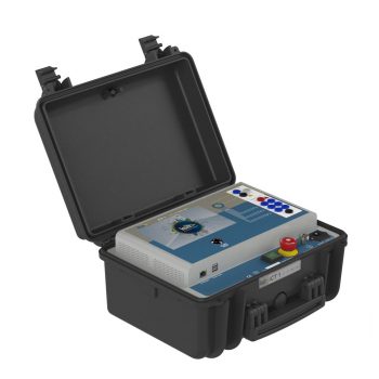
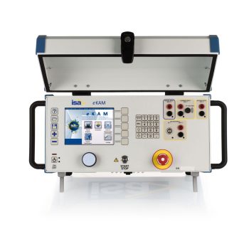
- Designed to test Current, Voltage and Combined Transformers
- Time saving testing: only 1 set up connection to perform all the tests
- Main tests performed: Ratio & Phase Error, Excitation, Resistance, Accuracy, Burden
- 5-TAP integrated Switchbox describing the behavior of the CT
- Able to test CT with saturation voltage up to 2kV and till 30kV applying DC indirect method
- Integrated Demagnetizer
- CT Explorer function: able to find the nameplate data of the CT
- Compact and lightweight
- Patented technology
Datasheet
|
- Control STS and TD remotely from PC
- Create test plan
- Download stored test results via Ethernet cable
- Create and customize test reports
- Print test results
Datasheet
|
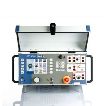
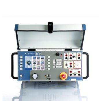
STS 4000 is a multifunction substation maintenance & commissioning test system for current, voltage and power transformers, designed to perform primary tests requested in substations commissioning. It allows to perform accurate tests on CTs, VTs, PTs and ground grid.
- Fully automatic
- Primary injection testing capabilities: up to 800 A or up to 5000 A / 7000 A, with the optional module BUX 5000
- Variable output frequency: 15 - 500 Hz
- Power dissipation factor test with the optional module TD 5000 ( voltage up to 12 kV)
- 2000 v AC high-pot test
- Local control by large color display
- PADS - Power Apparatus Diagnostic Software for automatic testing, assessment and report
- IEC 61850-9-2 communication protocol
- Patented technology for Capacitance and Tan Delta measurement
- USB interface and Ethernet interface for PC connection.
- Compact and lightweight
Datasheet |
- Fully automatic
- Primary injection testing capabilities: up to 800 A or up to 5000 A / 7000 A, with the optional module BUX 5000
- Variable output frequency: 15 - 500 Hz
- Power dissipation factor test with the optional module TD 5000 ( voltage up to 12 kV)
- 2000 v AC high-pot test
- Local control by large color display
- PADS - Power Apparatus Diagnostic Software for automatic testing, assessment and report
- IEC 61850-9-2 communication protocol
- Patented technology for Capacitance and Tan Delta measurement
- USB interface and Ethernet interface for PC connection.
- Compact and lightweight
Datasheet |
- High current output up to 7000 A
- Powerful output up to 35 kVA
- Modular design for easy transport
- Primary current injection testing
- Protection relay testing
- Low voltage breaker testing
- CT testing
- Heat runs
Datasheet
|
Instrument Transformer Testing (CT / VT Testing)
Instrument transformer testing involves verification, calibration and functional testing of current transformers (CT) and voltage or potential transformers (VT/PT) in power networks. Test instruments supply defined currents and voltages to verify transformation ratio, accuracy, phase shift, insulation strength, load behaviour and overall functionality under operating conditions.
FAQ
What is instrument transformer testing?
It is the procedure for testing current and voltage transformers (CT/VT/PT) to verify their transformation accuracy, phase relationship, insulation integrity and operational reliability.
Why is testing of transformers necessary?
Transformers provide critical measurements for metering and protection. Faulty or inaccurate transformers can lead to incorrect measurements, misoperation of protection systems or network instability. Regular testing ensures safety and accuracy.
Which transformer types are tested?
Current transformers (CT), voltage/potential transformers (VT/PT), combined measurement and protection transformers and transformer assemblies in switchgear or distribution systems.
Which parameters are measured during testing?
Transformation ratio, accuracy (ratio & phase), leakage current, load response, insulation resistance, open-/short-circuit behaviour, thermal performance, and, if applicable, secondary outputs under load or fault conditions.
What does a typical test sequence look like?
Visual inspection and identification, connection to test set, injection of defined primary current/voltage, measurement of secondary outputs, comparison with nominal values, phase-shift and error analysis, insulation test, load and short-circuit tests, documentation.
Why are ratio and phase angle important?
Ratio ensures correct scaling of primary to secondary values; phase angle must be accurate to maintain proper synchronization for protection and measurement systems — crucial for three-phase grids and protection coordination.
How is insulation strength tested?
By applying a defined test voltage between primary, secondary and earth to check insulation integrity, shielding and isolation between windings and grounded parts — preventing breakdown or faults.
How are results evaluated?
Measured values are compared with manufacturer specs or standards. Deviations beyond tolerance — ratio error, phase shift, insulation failure — indicate rejection or need for repair.
How often should instrument transformers be tested?
Recommended at commissioning, after maintenance or repairs, after modifications, after major events (faults, overloads) or at periodic intervals per regulation or grid operator policy.
Who should perform these tests?
Qualified electrical engineers or protection & metering technicians experienced in medium/high-voltage systems, CT/VT testing and safety procedures.
Which test equipment is used?
Multi-channel test sets with high current/voltage sources, measurement modules, load simulation capability, insulation test modules, software-based control and documentation tools.
What is the difference between primary and secondary testing?
Primary test injects current/voltage through the actual primary circuit (real load); secondary test applies signals directly to transformer secondary terminals or relay inputs — useful during maintenance without disrupting supply.
When is secondary testing appropriate?
When the primary circuit cannot be de-energized or taken offline — allows verification of ratio, phase, insulation and relay-side behaviour without interrupting operation.
Which documentation is required?
Test reports with transformer data (type, ratio), test conditions (current/voltage, load), measured values, tolerances, date, tester and verdict. This ensures traceability and reference for future inspections.
Does temperature affect test results?
Yes — temperature influences winding resistance and insulation properties. Tests should be done under defined conditions or with temperature recorded for later evaluation.
What to do if deviations are detected?
Disassemble the transformer, inspect windings and insulation, perform maintenance or replacement, then repeat tests to verify compliance before reconnection.
Which standards and safety procedures apply?
Standards for medium/high-voltage testing, insulation testing, earthing, isolation and operational safety must be followed. Tests must be done by trained personnel under safe, defined conditions.

Datenblatt