


- Process- and system-specific solutions possible
- Operating conditions: - Operating temperature: T = -10°C ...+70 °C (+158 °F) - Operating pressure: ambient
- Lengths: up to 20 m (65 ft)
- Humidity: 100 %
- Operational radiation dose: ≤ 160 kGy (16 MRad)
 Datasheet Datasheet |
- Compact and space-saving design
- Output signal 4 ... 20 mA (NAMUR NE43) or HART® ver. 6
- Operating limits: - Operating temperature: T = -40 ... +250 °C - Operating pressure: P = Vacuum to 40 bar - Limit density: ρ ≥ 580 kg/m3
- Explosion-protected version (option)
- Vibration resistant version (option)

| Datenblatt |
| Bedienungsanleitung |
| Bedienungsanleitung |
- Compact and space-saving design for industrial applications
- Output signal 4 ... 20 mA (NAMUR NE43)
- Operating limits - Operating temperature T = -40 ... +125 °C - Operating pressure P = Vacuum to 40 bar - Limit density ρ ≥ 680 kgm3
| Datasheet |
| User Manual |
- Fully welded and dead space free
- Operating limits: - Operating temperature: T = -40 ... +250 °C - Operating pressure: P = Vacuum to 10 bar
- Insensitive to foaming, ideal for interface measurement
- High-precision level measurement: Accuracy < 0.5 mm
- Wide variety of hygienic process connections
| Datasheet |
| User Manual |
| User Manual |
- Process- and procedure-specific solutions possible
- Operating limits: - Operating temperature: T = -80 ... +200 °C [-112 ... +392 °F] - Operating pressure: P = Vacuum to 25 bar [362,6 psi] - Limit density: ρ ≥400 kg/m3 [25,0 lbs/ft3]
- Wide variety of different electrical connections, process connections and materials
- Optionally with programmable and configurable head-mounted transmitter for 4 ... 20 mA field signals, HART®, PROFIBUS® PA and FOUNDATION™ Fieldbus
- Explosion-protected versions (option)
| Datasheet |
| User Manual |
| User Manual |
- Process- and procedure-specific solutions possible
- Operating limits: - Operating temperature: T = -80 ... +200 °C [-112 ... +392 °F] - Operating pressure: P = vacuum to 80 bar [1,160.3 psi] - Limit density: ρ ≥ 400 kg/m3 [25.0 lbs/ft³]
- Wide variety of different electrical connections, process connections and materials
- 4 ... 20 mA output signal with additional Bluetooth® interface for wireless configuration and level monitoring
| Datasheet |
| User Manual |
| User Manual |
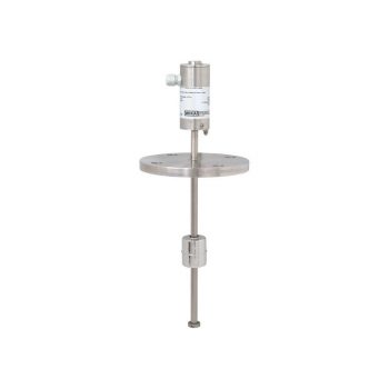
- IIoT-capable measuring instrument in combination with WIKA radio unit, model NETRIS®3
- Process- and procedure-specific solutions possible
- Operating limits:
- Process temperature:T = -80 ... +200 °C [-112 ... +842 °F]
- Operating pressure: P = vacuum to 80 bar [1,160 psi]
- Limit density: ρ ≥ 400 kg/m3
- Wide variety of different process connections and materials
- Intrinsically safe version Ex i
| Datasheet |
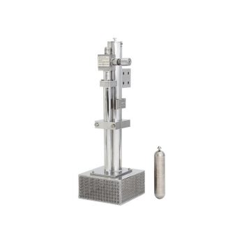
- Media compatibility: Oil, water, diesel, refrigerants and other liquids
- Permissible medium temperature range: -30 ... +120 °C [-22 ... +248 °F]
- Output signal: Resistance in a 3-wire potentiometer circuit, current output 4 ... 20 mA
- Measuring principle: Reed-chain technology
- Accuracy, resolution: 24 mm [0.9 in], 12 mm [0.5 in], 10 mm [0.4 in], 6 mm [0.2 in] oder 3 mm [0.1 in]
| Datasheet |
| User Manual |
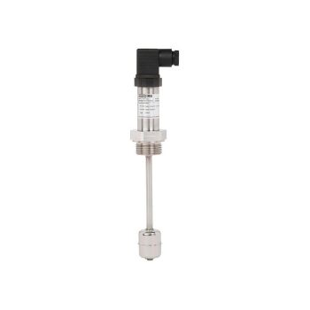
- Media compatibility: aqueous media and corrosive liquids
- Wetted parts: PP or PVDF
- Output signal: Resistance in a 3-wire potentiometer circuit, current output 4 ... 20 mA
- Accuracy, resolution: 24 mm [0.9 in], 12 mm [0.5 in], 10 mm [0.4 in], 6 mm [0.2 in] or 3 mm [0.1 in]
| Datasheet |
| User Manual |
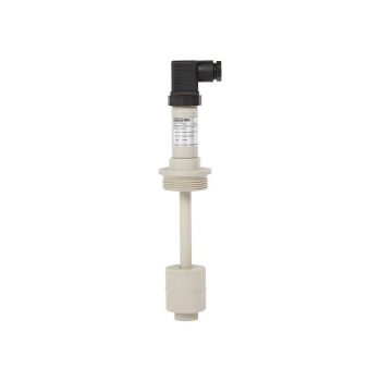
- Media compatibility: Oil, water, diesel, refrigerants and other liquids
- Level: Current output 4 ... 20 mA
- Temperature: Pt100, Pt1000, accuracy: Class B
| Datenblatt |
| Bedienungsanleitung |
- Process- and procedure-specific solutions possible
- Operating limits: - Operating temperature: T = -90 ... +450 °C [-130 ... +842 °F] - Operating pressure: P = vacuum to 100 bar [1,450.4 psi] - Limit density: ρ ≥ 400 kg/m3 [25.0 lbs/ft³]
- Resolution < 0.1 mm
- Wide variety of different electrical connections, process connections and materials
- Explosion-protected versions
| Datasheet |
| User Manual |
| User Manual |
| User Manual |
- Process- and system-specific solutions possible
- Operating limits: - Operating temperature: T = -80 ... +200 °C - Operating pressure: P = Vacuum up to 80 bar - Limit density: ρ ≥400 kg/m3
- Wide variety of different electrical connections, process connections and materials
- Optionally with programmable and configurable head-mounted transmitter for 4 ... 20 mA field signals, HART®, PROFIBUS® PA and FOUNDATION™ Fieldbus
- Explosion-protected versions (option)

| Datasheet |
| Datasheet |
| User Manual |
| User Manual |
| User Manual |
