 User Manual
The Current Monitoring Relay monitors AC/DC current signals and mV signals for MIN and MAX Alarm and transmits the limit value message to the switching output.
The configuration is carried out via DIP switches or via the front programming interface (requires DZU 1201, see accessories). The monitoring relay has an adjustable switch-on delay, switch-off delay and a wiper function. Further settings such as latch function and window function are also possible.
Power can be supplied via the connection terminals or via the optional In-Rail-Connector (see accessories). The switching status and the device status are indicated by LEDs on the front panel. If the device is operated via the In-Rail Connector, a group message is available.
Product line
| Device Type | Order No. |
|---|---|
| Current Monitoring Relay, Relay, configurable per DIP switch | DG 35300 S |
| Current Monitoring Relay, Relay, configurable per DIP switch, In-Rail-Bus for power supply and group message |
DG 35300 B |
| Current Monitoring Relay, Transistor, configurable per DIP switch | DG 35380 S |
| Current Monitoring Relay, Transistor, configurable per DIP switch, In-Rail-Bus for power supply and group message |
DG 35380 B |
Technical Data
Input
| Current Input | mV Input | |
| Input signal 1) Monitoring range |
0 to 5 A AC/DC 0 to 5500 mA |
0 to 150 mV 0 to 165 mV |
| Input resistance | 0.01 Ω | 100 kΩ |
| Over load | < 10 A (< 30 A for 1 s) | < 30 V |
Output
| DG 35300 Relay (SPST) |
250 V AC / 30 V DC / 2 A Recommended minimum load 300 mW / 5 V / 5 mA |
| DG 35380 Transistor (Open-Collector) |
36 V DC / 50 mA, Residual voltage < 1.5 V ated not current limited |
| Switching functions | Make contact, break contact Normal, Latch |
| Time function | On delay: Off, 1 s, 2 s, 3 s, 5 s, 10 s, 20 s, 30 s |
| Resonse time | ≤ 20 ms |
| Switch state indicator | Yellow LED on front |
| Group message | Signal at In-Rail-Connector E (supply circuit) at device failure and alarm |
General Data
| Switching error | DC: < 0.2 % full scale AC: < 0.5 % full scale |
|
| Temperature coefficient | < 100 ppm/K | |
| Test voltage | 3 kV AC, 50 Hz, 1 Min., Input against output against power supply/In-Rail-Connector |
|
| Working voltage 1) (Basic Insulation) |
600 V AC/DC for overvoltage category II and pollution degree 2 acc. to EN 61010-1 |
|
| Protection against electrical shock 1) | Protective Separation by reinforced insulation acc. to EN 61010-1 up to 300 V AC/DC for overvoltage category II and contamination class 2 between input and output and power supply. |
|
| Ambient temperature | Operation Transport and storage |
–25 °C to +70 °C (-13 to +158 °F) –40 °C to +85 °C (-40 to +185 °F) |
| Power supply | 24 V DC, 16.8 V to 31.2 V DC, max. 1.0 W | |
| EMC 2) | EN 61326-1 | |
| Construction | 6.2 mm (0.244″) housing, protection class IP 20, mounting on 35 mm DIN rail acc. to EN 60715 | |
| Connection | Captive plus-minus clamp screws Wire cross-section 0.5 to 2.5 mm2 / AWG 20-14 Stripped length 8 mm / 0.3 in Screw terminal torque 0.6 Nm / 5 lbf in |
|
| Weight | Approx. 70 g | |
- As far as relevant the standards and rules mentioned above are considered by development and production of our devices. In addition relevant assembly rules are to be considered by installation of our devices in other equipment’s. For applications with high working voltages, take measures to prevent accidental contact and make sure that there is sufficient distance or insulation between adjacent situated devices.
- Minor deviations possible during interference
Block diagram

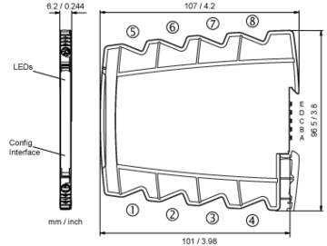
Dimensions
Terminal assignments
- 1 +Reset
- 2 +mV input
- 3 −GND
- 4 +Current input
- 5Relay
- 6Relay
- 5 +Transistor output
- 6 −Transistor output
- 7 +Power supply 24 V DC
(connected to In-Rail-Bus) - 8 −Power supply 24 V DC
(connected to In-Rail-Bus)
Optional power connection via In-Rail-Bus (see accessories)


