


 Datasheet
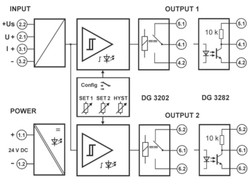
Two switching outputs can be configured simultaneously or independently of each other with the analog control electronics as MIN or MAX alarm in open-circuit or closed-circuit operation.
All setting elements are located behind the openable front cover and can also be operated when the unit is mounted. The switching points and the switching hysteresis can be adjusted with potentiometers. The monitoring states are indicated by yellow LEDs.
Two relay changeover contacts are available on the DG 3202. The DG 3282 is equipped with two isolated transistor switching contacts (open-collector), which can optionally work with pull-up resistors. Input, power supply and the outputs are safely galvanically isolated from each other.
The Protective Separation and the 24 V DC power supply make the DG 3202 and DG 3282 universally applicable for all measurement and industrial applications, as well as for building automation.
Product line
| Device | Order No. |
|---|---|
| Limit Value Monitor with relay contacts | DG 3202 |
| Limit Value Monitor with transistor switches | DG 3282 |
Technical Data
Input
| Input signal | 0(4) … 20 mA | 0 … 10 V |
| Input resistance | Current input approx. 5 Ω | Voltage input approx. 120 kΩ |
| Overload max. | Current input 200 mA | Voltage input 300 V |
| Transmitter supply +Us | 16 V at UPower = 24 V, (13 V … 22 V depending on the supply voltage) current limited ≤ 30 mA |
|
| Switch point setting | 0 to 110 % with 12-turn potentiometer, independently adjustable for each switching output | |
| Hysteresis setting | 0 to 6 % or 0 to 60 % of measuring range switchable, adjustable with potentiometer | |
Output
| DG 3202 (Relay): | |
| Contact type | 2 changeover relays (SPDT) |
| Switching capability AC max. | 250 V / 6 A, 1500 VA |
| Switching capability DC max. | 250 V / 0.2 A, 115 V / 0.3 A, 30 V / 6 A Recommended minimum load 300 mW / 5 V / 5 mA |
| DG 3282 (Transistors): | |
| Contact type | 2 transistor switches, fully isolated, optional 10 kΩ Pull-up resistor |
| Switching capability | 30 V DC, max. 50 mA, residual voltage < 1.5 V, not current limited |
| Status indication | one yellow LED per switching output |
| Response time | approx. 20 ms |
General Data
| Switch error | < 0.2 % full scale | |
| Temperature coefficient 1) | < 150 ppm/K | |
| Test voltage | 4 kV, 50 Hz, 1 min. input against power supply against both switching outputs 3 kV, 50 Hz, 1 min. switching output 1 against switching output 2 |
|
| Working voltage 2) (Basic Insulation) |
1000 V AC/DC for overvoltage category II and 600 V AC/DC for overvoltage category III acc. to EN 61010 and pollution degree 2 between input, power supply and both switching outputs. Furthermore 300 V AC/DC between output 1 and output 2. | |
| Protection against electrical shock 2) | Protective separation according to DIN EN 61140 by reinforced insulation according to DIN EN 61010 up to 600 V AC/DC at overvoltage category II and 300 V AC/DC at overvoltage category III at pollution degree 2 between input, power supply and both switching outputs. Furthermore 300 V AC/DC between output 1 and output 2. | |
| Power supply | 24 V DC, ± 15 %, approx. 1.0 W | |
| Ambient temperature | Operation Transport and storage |
–20 °C to +60 °C (-4 to +140 °F) –35 °C to +85 °C (-31 to +185 °F) |
| EMC 3) | EN 61326 -1 | |
| MTBF (acc. to EN 61709 / SN 29500) | 575.4 years (Tamb. 40 °C, FIT 198) | |
| Construction | 12.5 mm (0.5″) housing, protection class IP 20, mounting on 35 mm DIN rail acc. to EN 60715 | |
| Connection | Captive plus-minus clamp screws, Wire cross-section max. 2.5 mm² / AWG 14 Stripped length 6 … 8 mm / 0.28 in, Screw terminal torque 0.8 Nm / 7 lbf in |
|
| Weight | 70 g | |
- Average TC related to full scale value in specified operating temperature range, reference temperature 23 °C
- For applications with high working voltages, ensure there is sufficient spacing or isolation from neighboring devices and protection against electric shocks.
- Minor deviations possible during interference
Block diagram
Dimensions
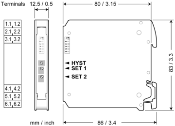
Terminal assignments
- 1.1 +Power supply +
- 1.2 −Power supply −
- 2.2 ++Us
- 2.1 +Voltage Input +
- 3.1 +Current Input +
- 3.2 −Input −
- Output 1
- 4.1COM Out+
- 4.2NO Out−
- 5.1NC Pull-Up
- Output 2
- 6.1COM Out+
- 6.2NO Out−
- 5.2NC Pull-Up


