


 Datasheet
The Modbus 4-channel relay module can be used to switch four electrically isolated relays via a Modbus interface. Various time functions can be used to influence the switching behaviour. All parameters can be set via Modbus RTU Interface. A subset of the most common settings is available via DIP switches.
The 5-way isolation guarantees reliable decoupling of the outputs from the processing circuit and the auxiliary power circuit. Auxiliary power and Modbus RTU must be connected via the In-Rail-Bus connector (see accessories).
Product line
| Device Type | Order No. |
|---|---|
| Modbus 4 Channel Relay Module, In-Rail-Bus for power supply and Modbus connection |
DMB 96800 B |
Technical Data
Output
| Relay 1, 2, 3, 4 | 250 V AC / 30 V DC / 2 A |
| Indication | Yellow LED for each channel on front panel |
Modbus
| Protocol | Modbus RTU (RS485) |
| Module addressing | 1 to 247 |
| Response delay | 1 to 1000 ms |
| Baudrate | 300, 600, 1200, 2400, 4800, 9600, 19200, 38400, 57600, 115200 |
| Configuration | Parity: Even, Odd, None with 2 Stop bits, None with 1 Stop bit |
| Connectivity | Up to 247 DRAGO Modbus devices without additional repeater (1/8 Load) |
| Indication | Yellow LED on front panel |
General Data
| Test voltage | 3 kV AC, 50 Hz, 1 min., All Relays against each other and against Modbus/power supply |
| Protection against dangerous body currents1) |
Protective Separation by reinforced insulation acc. to DIN EN 61010-1 up to 300 V AC/DC for overvoltage category II and contamination class 2 between input and Modbus/power supply |
| Ambient temperature | Operation: -25 °C to +70 °C (-13 to +158 °F) Transport and storage: -40 °C to +85 °C (-40 to +185 °F) |
| Power supply | 24 V DC, voltage range 16.8 V to 31.2 V DC, approx. 0.7 W |
| EMC2) | EN 61326-1 |
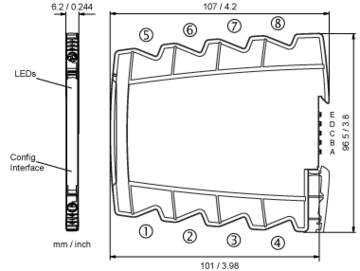
| Construction | 6.2 mm (0.244″) housing, protection type: IP 20, mounting on 35 mm DIN rail acc. to EN 60715 |
| Connection (captive plus-minus clamp screws) |
Solid: 0.5 mm² – 4 mm² / AWG 20-12 Fine-stranded: 0.5 mm² – 2.5 mm² / AWG 20-14 Stripped length: 6-8 mm / 0.28 in Screw terminal torque 0.8 Nm / 7 lbf in |
| Weight | Approx. 70 g |
- As far as relevant the standards and rules mentioned above are considered by development and production of our devices. In addition relevant assembly rules are to be considered by installation of our devices in other equipment. For applications with high working voltages, take measures to prevent accidental contact and make sure that there is sufficient distance or insulation between adjacent situated devices.
- Minor deviations possible during interference
Block diagram
Dimensions
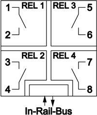
Terminal assignments
- 1Relay 1
- 2Relay 1
- 3Relay 2
- 4Relay 2
- 5Relay 3
- 6Relay 3
- 7Relay 4
- 8Relay 4
- AModbus A
- BModbus B
- C −Power supply 24 V DC
- D +Power supply 24 V DC


