


 Datasheet
The repeater power supply supplies the transmitter with power and transmits the current or voltage measuring signal with high accuracy galvanic isolated to the output. Alternative the measuring input accepts active signals from 4-wire transmitters.
The input and output range of DC 52100 can be easily set by using DIP switch. Due to the calibrated range selection no further adjustment is necessary.
The auxiliary power can be supplied via the connection terminals or via the optional In- Rail-Bus connector. A green LED on the front of the unit has been provided to monitor the power supply.
Product line
| Device Type | Order No. |
|---|---|
| Repeater Power Supply, calibrated range selection | DC 52100 S |
| Repeater Power Supply, calibrated range selection, In-Rail-Bus for power supply |
DC 52100 B |
Technical Data
Input
| Input signal (calibrated switchable) |
0 to 20 mA, 4 to 20 mA, 0 to 10 V, 2 to 10 V | |
| Input resistance | Current input ≤ 25 Ohm | Voltage input ≥ 100 kOhm |
| Overload | 50 mA / 30 V | |
| Transmitter supply (Tx) | 16 V (open circuit voltage/short circuit current < 22 V/35 mA) | |
Output
| Output signal (calibrated switchable) |
0 to 20 mA, 4 to 20 mA, 0 to 10 V, 2 to 10 V | |
| Load | Current output Voltage output |
≤ 12 V (600 Ohm at 20 mA) ≤ 5 mA (2 kOhm at 10 V) |
| Linear transmission range | –1 to +110 % | |
| Residual ripple | < 10 mVrms | |
General Data
| Transmission error | < 0.1 % full scale | |
| Temperature coefficient 1) | < 100 ppm/K | |
| Cut-off frequency -3 dB | 5 kHz, 100 Hz, switchable | |
| Response time T99 | 150 µs, 7 ms | |
| Test voltage | 3 kV AC, 50 Hz, 1 min, Input against output against power supply |
|
| Working voltage 2) (Basic Insulation) |
600 V AC/DC for overvoltage category II and pollution degree 2 acc. to EN 61010-1 |
|
| Protection against electrical shock 2) | Protective separation according to EN 61140 by reinforced insulation in accordance with EN 61010-1 up to 300 V AC/DC for overvoltage category II and pollution degree 2 |
|
| Ambient temperature | Operation Transport and storage |
–25 °C to +70 °C (-13 to +158 °F) –40 °C to +85 °C (-40 to +185 °F) |
| Power supply | 24 V DC, 16.8 V to 31.2 V DC, approx. 1.3 W | |
| EMC 3) | EN 61326-1 | |
| Approvals | UL (USA/Canada): UL 61010, Class I, Div. 2 ATEX / IECEx: Zone 2 (nA) |
|
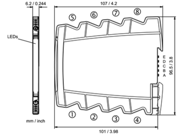
| Construction | 6.2 mm (0.244″) housing, protection class: IP 20 mounting on 35 mm DIN rail acc. to EN 60715 |
|
| Connection | Captive plus-minus clamp screws Wire cross-section max. 2.5 mm² / AWG 14 Stripped length 6 to 8 mm / 0.28 in Screw terminal torque 0.8 Nm / 7 lbf in |
|
| Weight | Approx. 70 g | |
- Average TC related to full scale value in specified operating temperature range, reference temperature 23 °C
- For applications with high working voltages, ensure there is sufficient spacing or isolation from neighboring devices and protection against electric shocks.
- Minor deviations possible during interference
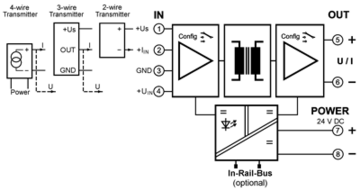
Block diagram
Dimensions
Terminal assignments
- 1 +Transmitter supply voltage U Tx
- 2 +Input current
- 3 −Input GND
- 4 +Input voltage
- 5 +Output
- 6 −Output
- 7 +Power supply 24 V DC
(connected to In-Rail-Bus) - 8 −Power supply 24 V DC
(connected to In-Rail-Bus)
Optional power connection via In-Rail-Bus (see accessories)


