 Datasheet
Due to the extremely slim design, the space requirement is only 3 mm per channel. The input and output ranges can be selected individually for each channel via DIP switches. A readjustment is not necessary due to the calibrated measuring ranges. A signal clipping and the cut-off frequency can also be set via DIP switches.
The power is supplied via the In- Rail-Bus, which ensures prewiring on a standard DIN rail. This significantly reduces the wiring effort. A green LED on the front of the unit has been provided to monitor the power supply.
Product line
| Device Type | Order No. |
|---|---|
| 2-Channel Isolation Amplifier | DN 26000 B |
In-Rail-Bus for power supply (see accessories)
Technical Data
Inputs
| Input signal (calibrated switchable) |
0 … 20 mA, 4 … 20 mA 0 … 10 V, 0 … 5 V |
|
| Input resistance | Current input Voltage input |
≤ 25 Ohm ≥ 100 kOhm |
| Overload | Current input Voltage input |
< 50 mA < 30 V |
Outputs
| Output signal (calibrated switchable) |
0 … 20 mA, 4 … 20 mA 0 … 10 V, 0 … 5 V |
|
| Load | Current output: Voltage output: |
≤ 10 V (500 Ohm at 20 mA) ≤ 5 mA (2 kOhm at 10 V) |
| Linear transmission range | -1 … +110 % | |
| Residual ripple | < 10 mVeff | |
General Data
| Transmission error | < 0.1 % full scale | |
| Temperature coefficient 1) | < 100 ppm/K | |
| Cut-off frequency -3 dB | 100 Hz 10 Hz (switchable) | |
| Response time T99 | 10 ms 55 ms | |
| Test voltage | 3 kV AC, 50 Hz, 1 min., Inputs against outputs against power supply |
|
| Working voltage 2) (Basic insulation) |
600 V AC/DC for overvoltage category II and pollution degree 2 acc. to EN 61010-1 |
|
| Protection against electrical shock |
Protective separation according to EN 61140 by reinforced insulation in accordance with EN 61010-1 up to 300 V AC/DC for overvoltage category II and pollution degree 2 between all circuits |
|
| Ambient temperature | Operation Transport and storage |
–25 °C to +70 °C (-13 to +158 °F) –40 °C to +85 °C (-40 to +185 °F) |
| Power supply | 24 V DC via In-Rail-Bus voltage range 16.8 V … 31.2 V DC, approx. 1.1 W | |
| EMC 3) | EN 61326-1 | |
| Construction | 6.2 mm (0.244″) housing, protection class IP 20, mounting on 35 mm DIN rail acc. to EN 60715 |
|
| Connection | Captive plus-minus clamp screws Wire cross-section 0.5 … 2.5 mm2 Stripped length 8 mm Screw terminal torque 0.6 Nm |
|
| Weight | Approx. 70 g | |
- Average TC related to full scale value in specified operating temperature range, reference temperature 23 °C
- For applications with high working voltages, ensure there is sufficient spacing or isolation from neighboring devices and protection against electric shocks.
- Minor deviations possible during interference
Block diagram

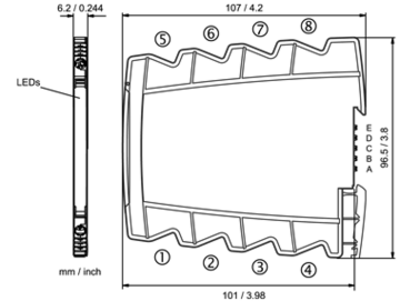
Dimensions
Terminal assignments
- Channel 1
- 1Input (+U/-I)
- 2Input (-U/+I)
- 5 +Output
- 6 −Output
- Channel 2
- 3Input (+U/-I)
- 4Input (+U/-I)
- 7 +Output
- 8 −Output
- D +Power supply In-Rail-Bus D
- C −Power supply In-Rail-Bus C
Power connection via In-Rail-Bus (see accessories)


