 Datenblatt
Its high level of reliability and cost optimized design make the DN 240M the first choice in customer applications.
Unique in its price class, the DN 240M provides application flexibility thanks to the calibrated range.
The desired input and output range can be easily set by terminal pins and due to the calibrated range selection no further adjustment is necessary.
The flat module with 15.5 mm height for pcb assembling saves space in the customer application.
Product line
| Device | Order No. |
|---|---|
| Isolation Amplifier Module, calibrated range selection | DN 240M |
Technical Data
Input
| Input signal | 0 to 20 mA, 4 to 20 mA, 0 to 10 V, terminal selectable | |
| Input resistance | Current input Voltage input |
22 Ohm 1 MOhm |
| Overload | Current input Voltage input |
≤ 100 mA Voltage limitation via 30 V Z-Diode, max. continuous current 30 mA |
Output
| Output signal | 0 to 20 mA, 4 to 20 mA, 0 to 10 V, terminal selectable | |
| Load | Current output Voltage output |
≤ 10 V (500 Ohm at 20 mA) ≤ 10 mA (1 kOhm at 10 V) |
| Residual ripple | < 20 mVrms | |
General Data
| Transmission error | < 0.3 % full scale | |
| Temperature coefficient 1) | < 150 ppm/K | |
| Cut-off frequency -3 dB | 1 kHz | |
| Response time T99 | 0.7 ms | |
| Test voltage | 2.5 kV, 50 Hz, 1 min., Input against output against power supply |
|
| Working voltage 2) (Basic Insulation) |
600 V AC/DC for overvoltage category II and pollution degree 2 acc. to EN 61010-1 |
|
| Ambient temperature | Operation Transport and storage |
–10 °C to +60 °C (+14 to +140 °F) –20 °C to +80 °C (-4 to +176 °F) |
| Power supply | 24 V DC ±10 %, approx. 1.2 W | |
| EMC 3) | EN 61326-1 | |
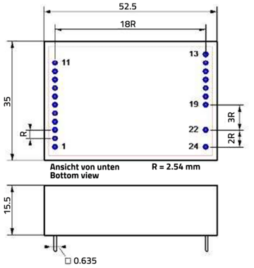
| Construction | Module for pcb assembling, 52.5 x 36 x 15.5 mm (l x w x h) | |
| Weight | Approx. 60 g | |
- Average TC related to full scale value in specified operating temperature range, reference temperature 23 °C
- For applications with high working voltages, ensure there is sufficient spacing or isolation from neighboring devices and protection against electric shocks.
- Minor deviations possible during interference
Block diagram

Dimensions
Klemmenbelegung
- 1 +Input voltage 0 … 10 V
- 2 −Input voltage
- 3 +Input current 0/4 … 20 mA
- 4 −Input current
- Output current
- 13
- 14+ Output
- 15– Output
- 16
- Output voltage
- 13
- 14+ Output
- 15– Output
- 16
- 17Jumper for Output 4 … 20 mA
- 18
- 19Jumper for Output 4 … 20 mA
- 22 −Power supply 24 V DC
- 24 +Power supply 24 V DC
] = Jumper on customer pcb
all other pins not connected


