


 Datasheet
For applications where one measuring range only is used, the Temperature Transmitter DR 44 offers a cost-effective alternative.
A cross-connector for the auxiliary power supply ensures fast and easy installation. The slim housing with 11.2 mm width saves significant space on the DIN-rail. If required a measuring range compensation can be performed at the Zero/Scan potentiometers behind the front cover.
Analog signal processing guarantees precise measured values with short response times and outstanding signal reproduction at the output.
Protective Separation and the 24 V AC/DC power supply make the Temperature Transmitter DR 44 universally applicable for all measurement and industrial applications, as well as for building automation.
Product line
| Devices | Sensor | Order No. | ||
|---|---|---|---|---|
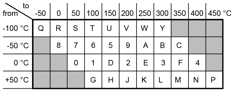
| Pt 100 | DR 44 P – | X | X | |
| Input | 0…+50 °C | 0 | ||
| 0…+100 °C | 1 | |||
| 0…+150 °C | D | |||
| 0…+200 °C | 2 | |||
| 0…+250 °C | E | |||
| 0…+300 °C | 3 | |||
| 0…+350 °C | F | |||
| 0…+400 °C | 4 | |||
| -50…0 °C | 8 | |||
| -50…+50 °C | 7 | |||
| -50…+100 °C | 6 | |||
| -50…+150 °C | 5 | |||
| -50…+200 °C | 9 | |||
| -50…+250 °C | A | |||
| -50…+300 °C | B | |||
| -50…+350 °C | C | |||
| -100…-50 °C | Q | |||
| -100…0 °C | R | |||
| -100…+50 °C | S | |||
| -100…+100 °C | T | |||
| -100…+150 °C | U | |||
| -100…+200 °C | V | |||
| -100…+250 °C | W | |||
| -100…+300 °C | Y | |||
| +50…+100°C | G | |||
| +50…+150°C | H | |||
| +50…+200°C | J | |||
| +50…+250°C | K | |||
| +50…+300°C | L | |||
| +50…+350°C | M | |||
| +50…+400°C | N | |||
| +50…+450°C | P | |||
| Output | 0 … 20 mA | 2 | ||
| 4 … 20 mA | 4 | |||
| 0 … 5 V | 5 | |||
| 1 … 5 V | 8 | |||
| 0 … 10 V | 6 | |||
| 2 … 10 V | 7 |
Technical Data
Input
| Sensor | Pt 100, 4-wire |
| Measuring range | Fixed ranges within -100 to +450 °C, see order information |
| Measuring error | < 0.1 K + 0.05 % of span |
| Sensor wire resistance | 25 Ohm |
| Sensor current | 1 mA |
Output
| Output signal | 0 to 20 mA, 0 to 5 V, 0 to 10 V, see order information 4 to 20 mA, 1 to 5 V, 2 to 10 V |
|
| Load | Current output Voltage output |
≤ 500 Ohm ≥ 2 kOhm |
| Residual ripple | < 10 mVrms | |
General Data
| Transmission error | < 0.1 % full scale | |
| Temperature coefficient 1) | < 0.025 %/K | |
| Zero/Span compensation | ± 3 % | |
| Response time T99 | < 2 ms | |
| Test voltage | 3 kV AC, 50 Hz, 1 min., input against output against power supply |
|
| Working voltage 2) (Basic Insulation) |
600 V AC/DC for overvoltage category II and pollution degree 2 acc. to EN 61010-1 |
|
| Protection against electrical shock 2) |
Protective separation according to EN 61140 by reinforced insulation in accordance with EN61010-1 up to 300 V AC/DC for overvoltage category II and pollution degree 2 between all circuits. |
|
| Ambient temperature | Operation Transport and storage |
–20 °C to +60 °C (–4 °F to +140 °F) –35 °C to +85 °C (–31 °F to +185 °F) |
| Power supply | 24 V AC/DC, ± 15 % | AC: 48 to 62 Hz, approx. 2 VA DC: approx. 0.7 W |
| EMC 3) | EN 61326 -1 | |
| Construction | 11.2 mm (0.44″) housing, protection class: IP 20 mounting on 35 mm DIN rail acc. to EN 60715 |
|
| Connection | Wire cross-section max. 2,5 mm² | |
| Weight | Approx. 50 g | |
- Average TC related to full scale value in specified operating temperature range, reference temperature 23 °C
- For applications with high working voltages, ensure there is sufficient spacing or isolation from neighboring devices and protection against electric shocks.
- Minor deviations possible during interference.
Block diagram
Dimensions

Terminal assignments
- 1Input Pt
- 2Input Pt
- 3Input 3-wire
- 4Input 4-wire
- 5 +Output
- 6 −Output
- 7Power supply 24 V AC/DC
- 8Power supply 24 V AC/DC


