Due to the easy selection of the input and output ranges, the new universal power supply and the ultra-small housing the Temperature Transmitter is suitable for flexible use. High reliability and Protective 3-Port-Separation are further characteristics that make the DR 4700 unrivaled.
The configuration of measurement range can be easily set within -100 to +600 °C by using DIP switch. Subsequent readjustment after range selection or measured range compensation can then be performed at the Zero/Span potentiometers on the front panel. Alternatively, the Temperature Transmitter is also available customer-specific adjusted.
The small housing with 12.5 mm width saves space in your switch cabinet and facilitates by the practical plug-in screw terminal blocks the assembly. For range setting a simple housing unblocking is installed which makes it possible to reach easily all control elements on the mounting rail.
The new universal power pack for 20 to 253 V AC/DC means the DR 4700 can be used anywhere in the world, with all mains power supplies. The unit’s high efficiency contributes significantly to reducing the unit’s own heat generation. This is reflected in extremely high reliability and long-term stability.
Product line
| Devices | Order No. |
|---|---|
| Temperature transmitter, min. span 50 K configurable (0 to 100°C pre adjusted) |
DR 4700 AG |
| Temperature transmitter, min. span 25 K configurable (0 to 100°C pre adjusted) |
DR 4720 AG |
Technical Data
Input
| Input signal | Pt 100 / Pt 1000, switchable |
| Sensor connection | 2-wire-, 3-wire-, 4-wire |
| Measuring range | |
| Zero | –100 °C,– 50 °C, 0 °C, 50 °C, switchable with Potentiometer ZERO 0 to 50 °C adjustable |
| Span | DR 4700 AG: 50 K, 100 K, 200 K, 300 K, switchable DR 4720 AG: 25 K, 50 K, 100 K, 150 K, switchable with Potentiometer SPAN 100 to 200 % of span adjustable |
| Sensor wire resistance | < 25 Ohm per wire |
| Sensor current | 1mA / 0.1 mA |
| Sensor diagnostic | Sensor / wire break |
Output
| Output signal | 0 to 20 mA, 0 to 5 V, 0 to 10 V switchable 4 to 20 mA, 1 to 5 V, 2 to 10 V |
|
| Load | Current output Voltage output |
≤ 12 V (600 Ohm at 20 mA) ≤ 5 mA (2 kOhm at 10 V) |
| Residual ripple | < 10 mVrms | |
| Sensor break action | Current output Voltage output |
≥ 22 mA ≥ 11 V |
General Data
| Linearity | < 0.2 % of measuring span | |
| Temperature coefficient 1) | < 150 ppm/K | |
| Calibration | Max. of ± 0.1 °C or 0.1 % of measuring span | |
| Response time T99 | < 20 ms | |
| Test voltage | 4 kV AC, 50 Hz, 1 min., input against output against power supply |
|
| Working voltage 2) (Basic Insulation) |
600 V AC/DC for overvoltage category II and pollution degree 2 acc. to EN 61010-1 |
|
| Protection against electrical shock 2) |
Protective separation according to EN 61140 by reinforced insulation in accordance with EN 61010-1 up to 300 V AC/DC for overvoltage category II and pollution degree 2 between all circuits. |
|
| Ambient temperature | Operation Transport and storage |
–10 to +60 °C (+14 to +140 °F) –20 to +80 °C (–4 to +176 °F) |
| Power supply | 20 to 253 V AC/DC, | AC 48 to 62 Hz, approx. 3 VA DC approx. 1.5 W |
| EMC 3) | EN 61326-1 | |
| Construction | 12.5 mm (0.49″) housing, protection type: IP 20 mounting on 35 mm DIN rail acc. to EN 60715 |
|
| Weight | Approx. 100 g | |
Factory setting: Input: Pt100, 4-wire, Output: 0 to 20 mA
- Average TC related to full scale value in specified operating temperature range, reference temperature 23 °C
- For applications with high working voltages, ensure there is sufficient spacing or isolation from neighboring devices and protection against electric shocks.
- Minor deviations possible during interference
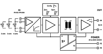
Block diagram

Dimensions

Terminal assignments
- 1 +Input Pt
- 2 −Input Pt
- 3 +3-wire
- 4 −4-wire
- 5 +Output
- 6 −Output
- 7Power supply AC/DC
- 8Power supply AC/DC
Pluggable screw clamp terminals
Wire cross-section max. 2.5 mm², Multi-wire connection max. 1 mm² (two wires with same cross-section)


 Datasheet


